
User Guide


3
Please contact 1-855-HD-HAMPTON for further assistance.
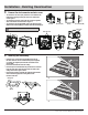
Typical Installation
Wiring Diagram
SPECIFICATIONS
Voltage: 120 V, 60 Hz
Airflow: 80/110 CFM
Duct diameter: 6 in.
Sound output: 0.6/0.8 Sones
The ducting from this fan to the outside of the
energy use of the fan. Use the shortest, straightest
duct routing possible for best performance, and
avoid installing the fan with smaller ducts than
recommended. Insulation around the ducts can
reduce energy loss and inhibit mold growth. Fans
installed with existing ducts may not achieve
WARNING: Wiring must comply with all applicable electrical
codes. Turn OFF power before removing or installing connectors
WARNING: COPPER TO COPPER ONLY. Do not use Aluminum wire.
OR
Roof cap (with
built-in damper)
Caulk
termination
to duct
Wall cap
(with
built-in
damper)
Properly insulate
around fan to
minimize building
heat loss and gain
Fan housing
Seal any gap around
fan housing
2-3 foot straight run
before elbow
duct helps alignment
and absorbs sound
fan
fan switch
(purchased separately)
120V line ACGround
black
blackwhite
ground
fan
The FAN wires
cannot be
connected to a
dimmer switch
Power consumption: 110CFM (35W), 80CFM (30W)
Weight: 9.77 lbs.
Ceiling Opening Dimension Requirements:
10 5/8 in. (L) x 10 5/8 in. (W).
90Ā
sensor
9.8ft
7ft
HOMEDEPOT.COM