
Installation Guide


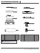


9
HAMPTONBAY.COM
Please contact 1-855-HD-HAMPTON for further assistance.
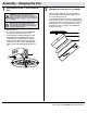
□ Attach a blade (D) to the fan motor assembly (C) by inserting the
blade (D) into slots in the side of the fan motor assembly (C) and
aligning the three screws holes in the blade with the holes in
the center ywheel and secure with screws (AA).
□ Make sure all the screws are rmly tightened.
□ Repeat these steps for the remaining blades.
Installing the motor assembly
□ Remove two of the four screws (located diagonally from
each other) (NN) from the top of the mounting plate (A)
and loosen the other two screws (NN).
□ Align the two key slots in the top of the fan motor
assembly (C) with the two loosened screws (NN) on the
mounting plate (A). Push the fan motor assembly (C) up
and turn it clockwise to lock in the mounting plate (A).
Tighten the two screws.
□ Install the two screws that were removed at the beginning
of this step into the remaining two holes and tighten the
four screws rmly.
□ Install the trim ring (B) by aligning the ring’s slots with
the screws on the mounting plate (A). Rotate the ring
clockwise to lock in place.
6
Attaching the blades
7
Assembly - Attaching the Blades
C
D
AA
Assembly - Hanging the Fan (continued)
Installing the receiver
5
□ Push the receiver (H) into the bracket on the mounting
plate (A) (as shown, at side towards the ceiling).
WARNING: To reduce the risk of re or electrical shock,
remember to disconnect power. The electrical wiring must meet
all local and national electrical code requirements. The electrical
source and fan must be 110/120 volt, 60HZ. Do not use this
product in conjunction with any variable wall control. Incorrect
wire connection can damage this receiver.
CAUTION: If other fan wires are different color, have this unit
installed by a licensed electrician.
CAUTION: Do not install the receiver (H) in a damp location or
immerse in water (For indoor use only). Do not pull on or cut
the receiver leads shorter. Do not drop or bump the unit.
A
C
B
NN
A
C
H
B