
Installation guide


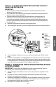


IMPORTANT : Si ni le trou A ni le trou B n'est aligné avec un montant,
localiser un montant à l'intérieur de la zone de la plaque de montage et
marquer un troisième trou aligné avec le montant.
5. Percer un trou aux emplacements du trou A et du trou B.
REMARQUE : Une vis à bois doit être utilisée lors d’une installation sur un
poteau de bois.
•
Percer un trou de ⁵⁄₈" pour utiliser un boulon à ailettes.
•
Percer un trou de ³⁄₁₆" pour utiliser une vis à bois.
6. Retirer la plaque de montage/gabarit du mur arrière et la mettre de côté. NE
PAS MONTER LA PLAQUE À CE MOMENT
3/8" TO EDGE
24” MINIMUM WIDTH REQUIRED
REAR WALL TEMPLATE
NOTE: IT IS VERY IMPORTANT TO
READ AND FOLLOW THE DIRECTIONS
IN THE INSTALLATION INSTRUCTIONS
BEFORE PROCEEDING WITH THIS
REAR WALL TEMPLATE.
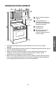
This Rear Wall Template serves to position the bottom
mounting plate and to locate the horizontal exhaust
outlet.
1. Use a level to check that the template is positioned
accurately.
2. Locate and mark at least one stud on the left or
right side of the centerline.
It is important to use at least one wood
screw mounted firmly in a stud to support the weight
of the microwave. Mark two additional, evenly spaced
locations for the supplied toggle bolts.
3. Drill holes in the marked locations. Where there is
a stud, drill a 3/16" hole for wood screws. For holes
that do not line up with a stud, drill 5/8" holes for
toggle bolts.
DO NOT INSTALL THE MOUNTING PLATE
AT THIS TIME.
4. Remove the template from the rear wall.
5. Review the Installation Instruction book for your
installation situation.
Locate and mark holes to align with holes in the
mounting plate.
IMPORTANT:
LOCATE AT LEAST ONE STUD ON EITHER SIDE OF
THE CENTERLINE.
MARK THE LOCATION FOR 2 ADDITIONAL, EVENLY
SPACED TOGGLE BOLTS IN THE MOUNTING PLATE
AREA.
Locate and mark holes to align with holes in the
mounting plate.
IMPORTANT:
LOCATE AT LEAST ONE STUD ON EITHER SIDE OF
THE CENTERLINE.
MARK THE LOCATION FOR 2 ADDITIONAL, EVENLY
SPACED TOGGLE BOLTS IN THE MOUNTING PLATE
AREA.
Trim the rear wall template along the dotted line.
Trim the rear wall template along the dotted line.
F. CUT OUT FOR HORIZONTAL
OUTSIDE EXHAUST
12"
4"
Darle vuelta a la hoja para consultar la
versión en Espa
ol.
e efa b
d
c
A
Trou A
B
Trou B
C
Tracer une ligne verticale sur le
mur depuis le centre du placard
supérieur.
D
Encoches de la ligne axiale
E
Tracer une ligne horizontale sur le
mur depuis le dessous du “gabarit du
mur arrière”.
F
Zone de la plaque de montage
ÉTAPE 5 - DÉTERMINER LA MÉTHODE DE
VENTILATION
IMPORTANT : Ce four à micro-ondes a été livré assemblé pour une
installation à ventilation par recyclage; Il est toutefois conçu pour être adapté
aux méthodes d’évacuation suivantes. Sélectionner la méthode d’évacuation
nécessaire pour votre installation et suivre les instructions
spéciques à votre
méthode :
38
FRANÇAIS