Installation & Operation Manual Central Air Conditioner 10 to 13 SEER 1.5 to 5 Tons Models: HC18-60A1VAR/S HC18-60C1VAR HC18-60D1VAR No.0010572324 K The information contained in this booklet is subject to change without notice. Downloaded from www.Manualslib.
! WARNING These instructions are intended as an aid to qualified, licensed service personnel for proper installation, adjustment and operation of this unit. Read these instructions thoroughly before attempting installation or operation. Failure to follow these instructions may result in improper installation, adjustment, service or maintenance possibly resulting in fire, electrical shock, property damage, personal injury or death.
TABLE OF CONTENT 1.Introduction --------------------------------------------------------------------------------------- 1 2.Nomenclature for Model Number ------------------------------------------------------------- 1 3.Specification ------------------------------------------------------------------------------------- 2 4.Unit Inspection ----------------------------------------------------------------------------------- 5 5.
Downloaded from www.Manualslib.com manuals search engine 850 Nominal RPM 2 23*23*24 Net Dimensions - In (mm) 23*23*24 63.60[1800] 23*23*31 1/2 88.34[2500] 3/4"[19.05] 3/8"[9.52] 1075 1/5 1.4 73 11.8 25 16.2 93.64[2650] 3/4"[19.05] 3/8"[9.52] 1075 1/5 1.4 88 14.
D W H Figure 1 Table 2:System Cooling Capacity Outdoor Unit Model Number With This Indoor Air handler Compressor Cooling Capacity (Btu/h) Sensible Total brand HB2400VA1M20 18000 Bristol 13000 Bristol HB2400VA1M20 24000 17000 HB3000VA1M20 28000 20000 Bristol Bristol HB3600VA1M20 34000 24000 HB4200VA1M25 Sanyo 40000 28400 Bristol 40500 29160 HB4800VA1M25 46000 Sanyo 33120 46000 33120 Bristol HB6000VA1M25 55800 Sanyo 40170 Bristol 56000 40180 Air Handler HC18A1VAR HC24A1VAR HC30A1VAR HC36A1VAS HC42A1VAR
Table 4:System Cooling Capacity Outdoor Unit Model Number With This Indoor Air handler Compressor Cooling Capacity (Btu/h) Sensible Total brand HB2400VC1M20 19000 Bristol 14820 Bristol HB2400VC1M20 24000 18720 HB3600VA1M20 30000 23400 Bristol Bristol HB3600VC1M25 36000 25920 HB4800VA1M25 Bristol 42000 30240 HB4800VA1M25 48000 34560 Bristol HB6000VC1M25 Bristol 58000 41800 Air Handler HC18C1VAR HC24C1VAR HC30C1VAR HC36C1VAR HC42C1VAR HC48C1VAR HC60C1VAR SEER 12 12 12 12 12 12 12 Rated CFM(Outdoor) 1950
4.UNIT INSPECTION This product has been inspected at the factory and released to the transportation agency without known damage. Inspect exterior of carton for evidence of rough handling in shipment. Unpack carefully. If damage is found, report immediately to the transportation agency. 5.EQUIPMENT PROTECTION FROM ENVIRONMENT The metal parts of the unit may be subject to rust or corrosion in adverse environmental conditions. This oxidation could shorten the unit life.
Provide a level concrete slab. To prevent transmission of noise or vibration, slab should not be connected to building structure. Some sort of sound-absorbing material should be placed between the condenser and the slab. A good material to use is rubber and cork pad. For rooftop application, make sure the building construction can support the weight and that proper consideration is given to the weather-tight integrity of the roof. The condensing unit contains moving parts and can vibrate.
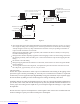
OUTDOOR UNIT ADDITIONAL SUCTION LINE OIL TRAP FOR EACH 20 FOOT PITCH SUCTION LINE TOWARD OUTDOOR UNIT 1/2" FRO EVERY 10' OF LINE RISE OF PIPE INDOOR UNIT ABOVE OR LEVEL TO OUTDOOR UNIT 70' LIQUID LINE MAX. SUCTION LINE OIL OUTDOOR UNIT LIQUID LINE TRAP WHEN INDOOR UNIT IS 4 FEET OR MORE BELOW OUTDOOR UNIT INDOOR UNIT A INDOOR UNIT INDOOR UNIT BELOW OUTDOOR UNIT 6' B-1 INVERTED LOOP LIQUID LINE INDOOR UNIT 50' MAX.
Refrigerant Line Sizing Check the following table (Table 7) for correct suction and liquid line sizes for any combination of the unit size and the maximum refrigerant line length. Refrigerant Line Length (Ft) Unit Size 0 - 24 25 - 49 50 - 74 (Ton) Line Outside Diameter (In) Seer Suction Liquid Suction Liquid Suction Liquid 10/12 1.5 5/8 3/8 3/4 3/8 3/4 3/8 13 3/4 3/8 3/4 3/8 7/8 1/2 10 2.0 5/8 3/8 3/4 3/8 3/4 3/8 12/13 3/4 3/8 3/4 3/8 7/8 1/2 2.5 3/4 3/8 3/4 3/8 7/8 1/2 10/12/13 3.
1.Tubing should be cut square. Make sure it is round and free of burrs at the connecting ends. Clean the tubing to prevent contamination from entering the system. 2.Make sure that both refrigerant stop valves at the outdoor unit are closed. 3.Push the tubing into the fitting until it stops. This prevents flux from getting into the system. 4.Remove the cap and Schrader valve core from the service port to protect the valve seals. 5.Wrap a wet rag around the valve stub before brazing. 6.
1.Fully open both shutoff valves. System Superheat 2.Connect service gage manifold to the valve service Ambient Return Air Temperature ( F) ports, being sure to evacuate lines. Temperature At 65 70 75 80 85 3.Startup the system (Refer to the Section 7 - "System Condenser Inlet ( F) Startup"). Run system at least 10 minutes to allo 60 17 25 30 33 37 pressure to stabilize. 65 13 19 26 32 35 70 5 14 20 28 32 4.Temporarily install thermometer on suction (large) 75 5 10 17 25 29 line near condensing unit.
The condensing unit rating plate and the tables of "Physical and Electrical Specifications / Outdoor Units" (Table 1 and 2) provide pertinent data necessary for the selection of proper size electrical service and over-current protection devices. Table 9 provides data on the minimum copper wire size as a function of supply wire length and circuit ampacity.
8.OPERATION Most single phase units are operated without start relay or start capacitor. Such systems should be off for a minimum of 5 minutes before restarting to allow equalization of pressures. The thermostat should not be moved to cycle unit without waiting 5 minutes. To do so may cause the compressor to stop on an automatic open overload device or blow a fuse. Poor electrical service can cause nuisance tripping in overloads or blow fuses. The compressor has an internal overload protector.
Symptom Possible Cause Power off or loose electrical connection Incorrect thermostat setting No cooling Defective contactor Open circuit breaker of blown fuses Defective transformer Interconnecting low voltage wiring damage Dirty filters Indoor air blockage Blocked outdoor coil Improperly sized unit Insufficient Cooling Improper airflow Incorrect refrigerant charge Air, non-condensibles or moisture in system Incorrect voltage Water on floor or in furnace Blocked condensate drain and "P" trap Run or start c
HC18-60A1VAR/S HC18-60C1VAR HC18-60D1VAR Air Conditioner Wi ri ng Diagram 5 C BRK L1 OFM 6 BK MR BR BK S YL 6 FL BK RD RD BR RD L2 BK BK PU RD RD WH L1 WH 1 2 3 4 5 6 BK 7 4 L2 GND RD WH 1 2 3 4 5 6 1 2 3 4 5 6 GND 208/230V 60Hz 1PH BL BR PU 208/230V 60Hz 1PH CC L2 TL RD BK BK TL RD RD L1 RD FL BK S R LINE VOLTA GE FACTORY STANDA RD FIELD INSTALLED OPTIONAL LOW VOLT AGE FACTORY STANDA RD FIELD INSTALLED OPTIONAL OPTIONAL ELECTRIC HEATER KIT BCR PU YL B
Made in P.R.C. Downloaded from www.Manualslib.