
Installation guide


INSTALLATION
PAGE 14
ENGLISH
Cassette Indoor Unit Specications
Cassette Product Information
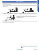
The Cassette Indoor Air Handler ships consists of a cassette
assembly and operational louver. The Cassette Indoor Unit
is operated via a factory supplied remote control. Wired
controller is optional.
The Cassette unit will install between standard dropped
brackets that are located at all four corners of the cassette
assembly.
The Cassette unit receives 230 volt line voltage from a
connection at the outdoor condensing unit. There is no
requirement for independent line voltage connections.
The cassette unit has a built in condensate pump and
Cassette unit. This hose connects the cassette condensate
drain outlet to the buildings condensate drain system.
The motorized louver is controlled via the remote control.
The louver has indicator lights that communicate function
and diagnostic information to the user and service technician.
Optional fresh air can be piped into the cassette assembly.
The knockout is located on the side of the cassette assembly.
entering the cassette. A 4” galvanized pipe should be used to
pipe in the fresh air.
Included with the cassette unit is factory provided insulating
tape. This tape should be placed over the refrigerant piping
connections at the indoor unit to prevent sweating.
Built-in Condensate
Pump and Float Switch
Factory Supplied
Remote
Wired Controller is
Optional
Outside Air
Mounting Hangers
Indoor Unit Installation - Cassette
Indoor AB09SC2VHA AB12SC2VHA AB18SC2VHA
Rated Cooling Capacity Btu/hr 9,000 12,000 18,000
Rated Heating Capacity Btu/hr 10,000 13,000 19,000
Voltage, Cycle, Phase V/Hz/- 208-230/60/1 208-230/60/1 208-230/60/1
Fan Speed Stages 5+Auto 5+Auto 5+Auto
Quiet) CFM
410/365/305/265/205 410/365/305/265/205 470/410/365/295/252
Motor Speed (Turbo/High/Med/Low/
Quiet) RPM
750/690/620/560/500 750/690/620/560/500 830/750/690/610/550
Indoor Sound Level dB (Turbo/High/
Med/Low/Quiet)
42/40/36/32/25 42/40/36/32/25 45/42/40/36/32
Grill Model PB-700IB PB-700IB PB-700IB
Chassis Dimension: Height in (mm) 10 1/4 (260) 10 1/4 (260) 10 1/4 (260)
Chassis Dimension: Width in (mm) 22 7/16(570) 22 7/16(570) 22 7/16(570)
Chassis Dimension: Depth in (mm) 22 7/16(570) 22 7/16(570) 22 7/16(570)
Grill Dimension: Height in (mm) 2 3/8 (60) 2 3/8 (60) 2 3/8 (60)
Grill Dimension: Width in (mm) 27 9/16 (700) 27 9/16 (700) 27 9/16 (700)
Grill Dimension: Depth in (mm) 27 9/16 (700) 27 9/16 (700) 27 9/16 (700)
Weight (Ship/Net)- lbs (kg) 46.3/37.5 (21/17) 48.5/40.8 (22/18.5) 48.5/40.8 (22/18.5)
Connections Flare Flare Flare
Liquid O.D. in 1/4 1/4 1/4
Suction O.D. in 3/8 3/8 1/2
Drainpipe Size O.D. in 1 1/4 1 1/4 1 1/4
Internal Condensate Pump Standard Standard Standard
Max. Drain-Lift height in(mm) 47 3/16(1,200) 47 3/16(1,200) 47 3/16(1,200)
Introduction - Overview