™ MX 30cc INSTRUCTION MANUAL SPECIFICATIONS Wingspan: 80 in [2030 mm] Length: 67 in [ 1700 mm] Weight: Wing Area: 1184 in2 [76.4 dm2] 12.75– 13.75 lbs [5780 – 6230 g] Radio: E i Engine: Wing Loading: 25– 27 oz/ft2 [76– 82 g /dm2] Electric: 4-6 6 Ch Chan Channel anne nell 1 8 2.0 2 0 cu iin [30 − 35 cc]] 1.8− RimFire 1.60 (63-62-250) Brushless WARRANTY Great Planes ® Model Manufacturing Co. guarantees this kit to be free from defects in both material and workmanship at the date of purchase.
TABLE OF CONTENTS INTRODUCTION . . . . . . . . . . . . . . . . . . . . . . . . . . . . . . . .2 SAFETY PRECAUTIONS . . . . . . . . . . . . . . . . . . . . . . . . .2 DECISIONS YOU MUST MAKE . . . . . . . . . . . . . . . . . . . .3 Engine Recommendations . . . . . . . . . . . . . . . . . . . . . .3 Motor Recommendations. . . . . . . . . . . . . . . . . . . . . . .3 Radio Equipment . . . . . . . . . . . . . . . . . . . . . . . . . . . . .3 ADDITIONAL ITEMS REQUIRED. . . . . . . . . . . . . . . . . . .
6. While this kit has been flight-tested to exceed normal use, if an engine larger than one in the recommended range is used, the modeler is responsible for taking steps to reinforce the high stress points and/or substituting hardware more suitable for the increased stress. Radio Equipment The Escapade MX 30cc ARF can be flown with a minimum of a 4-channel radio. For our installation we used six channels. One channel each for the throttle, choke, elevator, rudder ailerons and flaps. 7.
ADDITIONAL ITEMS REQUIRED Optional Supplies and Tools Required Hardware and Accessories Here is a list of optional tools mentioned in the manual that will help you build the Escapade MX 30cc ARF. ❍ (1) Dubro #554 X-Large Tygon Fuel Line (DUBQ0427) ❍ 2 oz. [57g] spray CA activator (GPMR6035) ❍ (1) R/C Foam Rubber (1/4" [6mm], HCAQ1000; or 1/2" [13mm], HCAQ1050) ❍ CA applicator tips (HCAR3780) ❍ Propeller and spare propellers suitable for your engine.
but can be purchased from hobby shops or mail order/Internet order firms. Hardware items (screws, nuts, bolts) are also available from these outlets. REPLACEMENT PARTS LIST Order No. GPMA5380 GPMA5381 GPMA5382 GPMA5383 GPMA5384 GPMA5385 GPMA5386 GPMA5387 GPMA5388 GPMA5389 GPMA5390 GPMA5391 To locate a hobby dealer, visit the Great Planes web site at www.greatplanes.com. Choose “Where to Buy”. Follow the instructions provided on the page to locate a U.S., Canadian or International dealer.
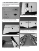
PREPARATIONS ❏ 1. Firmly pull on each of the control surfaces to confirm they are securely glued. ❏ 2. Tighten the covering with a covering iron as needed. ASSEMBLE THE WING Aileron Servo Installation Begin with the left wing panel. ❏ ❏ 3. Route servo lead through wing. ❏ ❏ 1. Install a servo lead extension (not included). ❏ ❏ 4. Drill servo screw mounting hole. ❏ ❏ 2. Install grommets and eyelets on all servos. ❏ ❏ 5. Install servo screws.
❏ ❏ 6. Install servo horn. ❏ ❏ 10. Position control horn on aileron. ❏ ❏ 7. Aileron pushrod components. ❏ ❏ 8. Install the 4-40 threaded clevis. ❏ ❏ 11. Mount control horn. ❏ ❏ 9. Attach clevis to control horn.
HOW TO SOLDER Apply a few drops of soldering flux to the end of the pushrod. “Tin” the end of the pushrod by applying heat. Apply silver solder to the heated area. The pushrod should melt the solder, not the flame of the torch. The end of the pushrod should be tinned all the way around. Position the solder clevis on the pushrod and apply a drop of flux to the joint. Apply heat and add solder. Again, the heat of the part should melt the solder, not the flame of the torch. Allow the part to cool naturally.
Flap Servo Installation (Optional) Flaps are not necessary to land the 30cc Escapade. However, if you have never flown with flaps, the 30cc Escapade is a great plane to learn with. ❏ 5. Install the flap servo following the same procedure used to install the aileron servos. ❏ 1. Install a servo lead extension (not included). ❏ 2. Install grommets and eyelets in the flap servo . ❏ 6. Install the flap servo in the right wing.
ASSEMBLE THE FUSELAGE Install the Tail A A A=A ❏ 5. Check the alignment of the horizontal stabilizer. The distance from the center of the nose of the fuselage to the tips of the horizontal stabilizer should be equal. ❏ 1. Slide the Carbon Wing Tube into the fuselage. ❏ 2. Install the wing panels. The wing and stabilizer should be parallel. If they are not, lightly sand the stabilizer slot. ❏ 3. Temporarily install the horizontal stabilizer and the vertical fin.
❏ 6. Use 30-minute epoxy to glue the stabilizer in the fuselage. ❏ 8. Glue the filler blocks on both sides of the fuselage. ❏ 9. Attach the tail gear to the fuselage. ❏ 7. Use 30-minute epoxy to glue the vertical fin in the fuselage.
❏ 10. Install the tail wheel. ❏ 2. Cut the axle to length. Install the Main Landing Gear ❏ 3. File a flat spot at the end of the axle. ❏ 1. Install the 3/16” [4.8mm] axles.
❏ 4. Install the main wheel. ❏ 6. Install the main landing gear on the fuselage. Install the Rudder and Elevator Servos ❏ 1. Install the rudder servo and plug it into the receiver. Temporarily plug the receiver battery into the receiver. ❏ 5. Install the wheel pants. ❏ 2. Install the rudder servo arm. ❏ 3. Cut the 114” [2900mm] pull-pull cable in half.
❏ 4. Install a 4-40 threaded coupler to the end of both pullpull cables. ❏ 5. Install a 4-40 nut and threaded clevis on the coupler. ❏ 8. Attach rudder control horns. ❏ 6. Insert the pull-pull cables in the pushrod guide tubes. Attach the clevises to the servo arm. ❏ 9. Attach a second set of clevises, 4-40 couplers, 4-40 7 ❏. Position the rudder control horn. nuts and silicone clevis retainers to the rudder control horns.
❏ 12. Install the elevator servos. Join the two servo leads with a Y-harness and plug the Y-harness into the receiver. ❏ 10. Pull the pull-pull cables tight and attach them to the rudder control horns. ❏ ❏ 13. Install the elevator control horns and attach the 4-40 clevises, nuts and retainers. 11. Install the elevator pushrods.
Electric Motor Installation Proceed to Engine and Tank Installation (page 19) if a gas engine will be installed. ❏ 14. Install the solder clevis. ❏ 1. Use epoxy to glue the front and back plates of the motor box together. ❏ 15. Solder the clevises to the elevator pushrods. ❏ 2. Install the 8-32 blind nuts and secure with CA.
❏ 3. Glue three of the sides on. ❏ 6. Open the cooling hole. ❏ 4. Glue eight pieces of triangle stock between the front ❏ 7. Attach the motor box to the firewall. plate and the sides and the back plate and the sides. Then, glue the fourth side on. ❏ 8. Install the RimFire 1.60 motor. ❏ 5. Drill the firewall.
❏ 9. Mount the ESC. Connect the wires from the ESC to the ❏ 14. Make two straps from the remaining hook and loop motor wires. material. Install the receiver, reciever switch and receiver battery. ❏ 15. Plug the ESC into the receiver. Check that the throttle is set to reverse on the Futaba transmitter. Plug the motor batteries into the ESC. Check that the motor turns counterclockwise. Skip to Install the Cowl. ❏ 10. Make two battery straps from the supplied hook and loop material.
❏ 6. Make three straps from the supplied hook and loop material. ❏ 3. Temporarily mount the engine using the hardware included with the engine. ❏ 7. Install the straps on the fuel tank tray. ❏ 4. Mark the fuel line, throttle and choke pushrod locations on the firewall. ❏ 8. Install the fuel tank tray. ❏ 5. Drill the firewall for the throttle, choke and fuel line. ❏ 9. Install the ignition switch. ❏ 10. Wrap the ignition battery and ignition module in foam rubber.
❏ 11. Install the ignition battery and ignition module. ❏ 12. Reinstall the engine. ❏ 15. Install the throttle and choke servos and plug them into the receiver. ❏ 16. Make two straps from the remaining hook and loop material. Install the receiver switch, receiver and receiver battery. ❏ 13. Use epoxy to assemble the throttle/choke servo tray. ❏ 17. Assemble the choke pushrod. ❏ 14. Glue the tray in the fuselage.
❏ 18. Install the choke pushrod. ❏ 22. Cut the outer pushrod tube. ❏ 23. Roughen the outer pushrod with sandpaper. ❏ 19. Assemble the choke clevis. ❏ 24. Install the outer pushrod. ❏ 20. Install the clevis on the choke servo. ❏ 25. Reinstall the clevis and adjust it so that the choke ❏ 21. Attach the 2-56x1" threaded rod to the choke pushrod. It is easier to remove the pushrod from the choke to install the threaded rod. 21 opens and closes completely.
❏ 3. Insert the brass tubes in the fuel tank stopper and stopper plates. ❏ 26. Install the throttle pushrod using the same procedure ❏ 4. Solder the barbs on the other end of the two shorter as used on choke pushrod. We recommend that a throttle cutoff also be set up on the transmitter to close the throttle completely, stopping the engine. brass tubes. Assemble the Fuel Tank ❏ 5. Bend the vent tube. ❏ 1. Clean both ends of the brass tubes with sandpaper. ❏ ❏ 6. 2.
Install the Fuel Tank ❏ 7. Loosely install the fuel tank stopper screw. ❏ 1. Install and mark the fuel lines: Vent, Carb and Fill. ❏ 2. Secure the fuel tank in the fuselage. ❏ 8. Slide the aluminum ring over the fuel tank neck. ❏ 9. Secure the fuel tank stopper in the fuel tank. Mark the ❏ 3. Route the fill line. top of the tank.
Install the Cowl For the electric installation, skip to step 2. ❏ 2. Position the cowl. ❏ 1. Trim the cowl to fit over the head and muffler. ❏ 3. Drill 5/64" [1.5mm] pilot holes. Attach the cowl using #4x5/8" [16mm] sheet metal screws and #4 flat washers. Apply the Decals 1. The decals are die-cut from the factory. 2. Be certain the model is clean and free from oily fingerprints and dust.
GET THE MODEL READY TO FLY 4-CHANNEL RADIO SET UP (STANDARD MODE 2) Check the Control Directions RUDDER MOVES RIGHT RIGHT AILERON MOVES UP LEFT AILERON MOVES DOWN FULL THROTTLE ELEVATOR MOVES DOWN ❏ 3. Make certain that the control surfaces and the carburetor respond in the correct direction as shown in the diagram. If any of the controls respond in the wrong direction, use the servo reversing in the transmitter to reverse the servos connected to those controls.
LESS THROW Pushrod Farther Out Pushrod Closer In MORE THROW Pushrod Closer In Pushrod Farther Out ❏ 4. Once the throws are set, apply a drop of threadlocker to the threads and tighten the 4-40 nuts against the clevises. Slide the silicone retainers over the clevises. IMPORTANT: Now that you have the throws set, be sure to set the failsafe on the radio. MORE THROW LESS THROW Install the Propeller ❏ 2. Adjust the location of the pushrod on the servo arm or on the control horn first.
Balance the Model (C.G.) DO NOT OVERLOOK THIS IMPORTANT PROCEDURE. A model that is not properly balanced may be unstable and possibly unflyable. 5-1/8" [130mm] 4-7/16" [113mm] ❏ 3. Install the spinner cone. ELECTRIC ONLY: Install the spinner adapter (GPMQ4584) before installing the spinner cone. ❏ 1. Mark the C.G range. ❏ 4. Install the canopy. Balance the Model Laterally ELECTRIC ONLY: Install the flight batteries, but do not plug the batteries into the ESC. ❏ 2.
leather glove, such as a welder’s glove. When hand starting gas engines, if the engine should backfire, the large prop can cause severe injury to your hand and fingers. PREFLIGHT Identify Your Model ● Do not run the engine in an area of loose gravel or sand; the propeller may throw such material in your face or eyes. You should always have your name, address, telephone number and AMA number on or inside your model. It is required at all AMA R/C club flying sites and AMA sanctioned flying events.
● ALWAYS charge a LiPo battery in a fireproof location. ● NEVER allow the battery temperature to exceed 150° F (65° C). 3) At all flying sites a straight or curved line(s) must be established in front of which all flying takes place with the other side for spectators. Only personnel involved with flying the aircraft are allowed at or in the front of the flight line. Intentional flying behind the flight line is prohibited. ● NEVER disassemble or modify the pack wiring in any way or puncture the cells.
Takeoff Before taking off, see how the model handles on the ground by doing a few practice runs at low speeds on the runway. Hold “up” elevator to keep the tail wheel on the ground. If necessary, adjust the tail wheel so the model will roll straight down the runway. Remember to takeoff into the wind. When you’re ready, point the model straight down the runway, hold a bit of up elevator to keep the tail on the ground to maintain tail wheel steering, then gradually advance the throttle.
Fill in your battery type, voltage and capacity. Then tape this chart to bottom of canopy hatch for reference: ELEVATOR Up/Down RUDDER Left/Right AILERON Up/Down HIGH RATE LOW RATE 7/8" [22mm] 13° 5/8" [16mm] 9° 2" [51mm] 19° 1-3/4" [44mm] 17° 3/4" [19mm] 17° 1/2" [13mm] 12° FLAP 7/8" [22mm] 20° Down 5/8" [8mm] elevator mixed with flap C.G.