
Installation Sheet


LIMITADOR DE TEMPERATURA
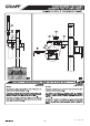
TEMPERATURE LIMITING DEVICE
5
30
6
The ring (TR) around the cartridge (7) allows the maximum output
temperature to be limited in order to avoid the accidental scalding.
The ring is factory pre-set to the highest setting allowing the
greatest flow of hot water (fig. 6.2).
7
8
9
10
11
The drawing presents a sample lever (10).
The levers may vary depending on the faucet design.
La figura representa la palanca ejemplar (10).
Puede diferenciarse en función del modelo del grifo.
6.1
6.2
6.3
6.4
2,5
El anillo (TR) alrededor del cartucho (7) limita la temperatu -
ra máxima del agua de salida con el fin de evitar quemaduras
casuales. El anillo está preajustado en la fabrica para permitir la
salida del flujo máximo de agua caliente (fig. 6.2).
TR
K1
Rev. 2 July 2014
To set the required
temperature:
Cut off the supply of hot and cold water to the faucet.
If the lever comes with a cap, remove the cap and then loosen the
bolt (11) with an Allen key (K1) and remove the lever from the
mixer shaft.
Unscrew the decorative shroud (9) and using a socket wrench
remove the nut (8).
Remove the temperature limiter (TR) and install it again, selecting
the appropriate setting:
turning the limiter anti-clockwise (Fig. 6.3) reduces the cold
water outflow,
turing the limiter clockwise (Fig. 6.4) reduces the hot
water outflow.
Set the limiter according to individual needs, turning it by a
smaller or greater angle.
Re-install the device performing the operations in a reverse order,
tighten the nut with a torque of 12-13 Nm (106-115 Ibf/in).
Open the supply of hot and cold water, check the facet for correct
operations and the set temperature limitations.
Cartige replacement
If there is a need to replace a used cartige, dismantle it following the
steps 1-3, and then replace the old cartige and re-install it
according to steps 5 and 6.
1.
2.
3.
4.
5.
6.
1.
2.
3.
4.
5.
6.
Para ajustar la
temperatura deseada:
Hay que cortar la entrada de agua caliente y fría a la batería.
Cuando la palanca tenga tapón hay que quitarlo y, luego, por medio
de la llave Allén (K1) soltar el tornillo (11) y quitar la palanca (10)
del perno del mezclador.
Destornille tapacubos decorativo (9) y, por medio de la llave de
vaso destornillar la tuerca (8).
Quitar el limitador de temperatura (TR) y volver a ponerlo seleccio-
nando el valor adecuado:
la revolución del limitador en sentido contrario a las agujas del
reloj (fig. 6.3) ocasiona la limitación de la salida del agua fría,
la revolución del limitador en sentido de las agujas del reloj
(fig. 6.4) ocasiona la limitación de la salida del agua caliente.
Hay que poner el limitador según las necesidades individu-
ales moviéndolo del ángulo menor o mayor.
El montaje del todo deberá realizarse en orden inverso y hay que
atornillar la tuerca con el par de torsión 12-13 Nm (106-115 Ibf/in).
Abrir la alimentación de agua fría y caliente, comprobar el
funcionamiento de grifo y las delimitaciones de temperatura.
Cambio de mezclador
En caso del reemplazo del mezclador gastado hay que realizar el desmonta-
je según los puntos: 1, 2, 3; luego, hay que reemplazar el mezclador
gastado y volver a realizar el montaje según los puntos 5 y 6.