
Install Instructions


24
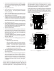
Hose #4
Hose #5
Hose #4
Hose #2
Figure 31
1. Remove the factory installed drain trap and hose
assemblies. Leave the 100° elbow inserted and
clamped in the vent-drain elbow.
2. Remove two 1”plugs from left side of cabinet
3. Drain the Collector Box. Remove the cap from the
left side of the collector box drain port (bottom in
horizontal left position) and install it on right side
drain port.
4. Place radius end of hose #4 (factory installed) on
the collector box drain port and secure with a silver
clamp.
5. Insert hose #2 from outside the cabinet in the front
drain hole.
6. Connect hose #4 & hose #2 together using a straight
barbed coupling and two gold clamps (factory
installed).
7. (Draining the Vent Elbow) Remove rubber plug from
vent – drain elbow side port.
8. The un-used vent-drain elbow drip leg port must
be plugged to prevent flue gases from escaping.
Insert rubber plug removed in step 7 into the 100°
elbow. (Inserting a blunt tool such as a 3/16” Allen
wrench into the center of the rubber plug will stretch
the plug and allow complete insertion).
9. Place radius end of hose #4 on the side port of vent
– drain elbow and secure with a gold clamp.
10. Insert a ½” diameter PVC pipe (factory installed)
into hose #4 and secure with a gold clamp.
11. Insert the non-grommet end of hose #5 (factory
installed) from outside the cabinet in the back drain
hole.
12. Insert 100º elbow in hose #5 and secure with a red
clamp.
13. Locate hose #4 and cut a cut off a 4” straight section
and discard the radius end.
14. Connect the 4” straight section of hose #4 to the
100º elbow and the PVC pipe and secure with red
clamps.
15. Connect the hoses to the trap inlets and secure with
silver clamps, drain trap outlet must point to the
original bottom of the furnace.
16. Using the two sheet metal screws provided in the
cabinet, secure the trap to the furnace.
17. Refer to Field Supplied Drain section for instructions
on field supplied / installed drain on outlet of furnace
trap.
CAUTION
T
O
PREVENT
UNRELIABLE
OPERATION
OR
EQUIPMENT
DAMAGE
,
THE
INLET
GAS
SUPPLY
PRESSURE
MUST
BE
AS
SPECIFIED
ON
THE
UNIT
RATING
PLATE
WITH
ALL
OTHER
HOUSEHOLD
GAS
FIRED
APPLIANCES
OPERATING
.
Natural Gas Minimum: 4.5" w.c. Maximum: 10.0" w.c.
Propane Gas Minimum: 11.0" w.c. Maximum: 13.0" w.c.
INLET GAS SUPPLY PRESSURE
G
AS
S
UPPLY
AND
P
IPING
The furnace rating plate includes the approved furnace gas input
rating and gas types. The furnace must be equipped to operate
on the type of gas applied. This includes any conversion kits
required for alternate fuels and/or high altitude.
Inlet gas supply pressures must be maintained within the ranges
specified in the following table. The supply pressure must be
constant and available with all other household gas fired appli-
ances operating. The minimum gas supply pressure must be
maintained to prevent unreliable ignition. The maximum must
not be exceeded to prevent unit overfiring.
P
ROPANE
G
AS
/H
IGH
A
LTITUDE
I
NSTALLATIONS
High
Stage
Low
Stage
Natural No ne # 45 3.5" w.c. 1.9" w.c. No ne
P ro pane
LP M -08*
1
1.25mm 10.0" w.c. 6.0" w.c. N o ne
M anifold P ressure
Pressure
Switch
Change
0-7000
1
LP M -08* suppo rts bo th Ho neywell and White-Ro dgers 2-stage valves
NOTE:
In C anada, gas furnaces are o nly certified to 4500 feet.
Gas A ltitude Kit Orifice
This furnace is shipped from the factory configured for natural
gas at standard altitude. Propane gas installations require an
orifice change to compensate for the energy content difference
between natural and propane gas.
For furnaces being converted to LP gas, it is strongly rec-
ommended that a LPLP03 kit also be installed. The use of
this kit will prevent the furnace from firing when the LP
gas supply pressure is too low to support proper combus-
tion.
High altitude installations may require both a pressure switch
and an orifice/spring change. These changes are necessary