
Installation Instructions


28
Complete information regarding tank sizing for vaporization,
recommended regulator settings, and pipe sizing is available
from most regulator manufacturers and propane gas suppliers.
Since propane gas will quickly dissolve white lead and most stan-
dard commercial compounds, special pipe dope must be used.
Always use a pipe thread sealant approved for all gases.
C
IRCULATING
A
IR
& F
ILTERS
DUCT WORK - AIR FLOW
Duct systems and register sizes must be properly designed for
the CFM and external static pressure rating of the furnace. De-
sign the ductwork in accordance with the recommended meth-
ods of “Air Conditioning Contractors of America” Manual D.
Install the duct system in accordance with Standards of the Na-
tional Board of Fire Underwriters for the Installation of Air Con-
ditioning, Warm Air Heating and Ventilating Systems. Pamphlets
No. 90A and 90B.
A closed return duct system must be used, with the return duct
connected to the furnace. NOTE: Ductwork must never be at-
tached to the back of the furnace. For upflow installations re-
quiring 1800 CFM or more, use either two side returns or bottom
return or a combination of side /bottom. Flexible joints may be
used for supply and return connections to reduce noise transmis-
sion. To prevent the blower from interfering with combustion air
or draft when a central return is used, a connecting duct must be
installed between the unit and the utility room wall. Never use a
room, closet, or alcove as a return air chamber.
When furnace duct(s) supply air outside the space contain-
ing the furnace, a return air duct must terminate in the
same space as the supply duct and be sealed to the furnace
casing.
CHECKING DUCT STATIC
N
EVER
ALLOW
THE
PRODUCTS
OF
COMBUSTION
,
INCLUDING
CARBON
MONOXIDE
,
TO
ENTER
THE
RETURN
DUCT
WORK
OR
CIRCULATION
AIR
SUPPLY
.
WARNING
Refer to your furnace rating plate for the maximum ESP
(external duct static) rating.
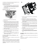
Total external static refers to everything external to the
furnace cabinet. Cooling coils, filters, ducts, grilles, reg-
isters must all be considered when reading your total ex-
ternal static pressure. The supply duct pressure must be
read between the furnace and the cooling coil. This read-
ing is usually taken by removing the “A” shaped block off
plate from the end on the coil; drilling a test hole in it
and reinstalling the block off plate. Take a duct static
reading at the test hole. Tape up the test hole after your
test is complete. The negative pressure must be read
between the filter and the furnace blower.
Too much external static pressure will result in insufficient
air that can cause excessive temperature rise. This can cause
limit switch tripping and heat exchanger failure.
To determine total external duct static pressure, proceed as
follows;
1. With clean filters in the furnace, use a draft gauge (in-
clined manometer) to measure the static pressure of the
return duct at the inlet of the furnace. (Negative Pressure)
2. Measure the static pressure of the supply duct. (Positive
Pressure)
3. The difference between the two numbers is .4” w.c.
For example:
-.1
0
.1 .2 .3
Difference is .4
.
.
Static reading from return duct = -.1" w.c.
Static reading from supply duct = .3" w.c.
Total external static pressure on this system =.4" w.c.
NOTE: Both readings may be taken simultaneously and read
directly on the manometer if so desired. If an air conditioner
coil or Electronic Air Cleaner is used in conjunction with the
furnace, the readings must also include theses components,
as shown in the following drawing.
4. Consult the proper tables for the quantity of air.
If the total external static pressure exceeds the maximum
listed on the furnace rating plate, check for closed dampers,
registers, undersized and/or oversized poorly laid out duct
work.
NOTE: The temperature rise of the furnace must be within
the temperature rise range listed on the furnace rating
plate.
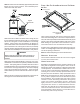
BOTTOM RETURN AIR OPENING [UPFLOW MODELS]
The bottom return air opening on upflow models utilizes a
“lance and cut” method to remove sheet metal from the duct
opening in the base pan. To remove, simply press out the
lanced sections by hand to expose the metal strips retaining
the sheet metal over the duct opening. Using tin snips, cut
the metal strips and remove the sheet metal covering the
duct opening. In the corners of the opening, cut the sheet
metal along the scribe lines to free the duct flanges. Using
the scribe line along the duct flange as a guide, unfold the
duct flanges around the perimeter of the opening using a pair
of seamer pliers or seamer tongs.