
Install Instructions


40
This tells us that at this rate, it would take 46 seconds to
consume one cu. ft. of gas. 3600 / 46 = 78.
This tells us that in one hour, the furnace would consume 78
cu. ft. of gas. The typical value range for 1 cu. ft. of natural
gas is around 1000 BTU. Check with your gas utility, if pos-
sible. In this example, the furnace is consuming 78,000 BTUH.
NOTE: The final manifold pressure cannot vary by more than
± 0.3” w.c. for Natural and + 0.5” for LP from the specified
setting. Consult your local gas supplier if additional input
rate adjustment is required.
4. Turn ON gas to and relight all other appliances turned
off in step 1. Be certain that all appliances are
functioning properly and that all pilot burners are
operating.
TEMPERATURE RISE
Temperature rise must be within the range specified on the unit
rating plate. An incorrect temperature rise may result in con-
densing in or overheating of the heat exchanger. An airflow and
temperature rise table is provided in the Specification Sheet ap-
plicable to your model. Determine and adjust temperature rise
as follows:
1. Operate furnace with burners firing for approximately ten
minutes. Ensure all registers are open and all duct dampers
are in their final (fully or partially open) position.
2. Place thermometers in the return and supply ducts as close
to the furnace as possible. Thermometers must not be
influenced by radiant heat by being able to “see” the heat
exchanger.
3. Subtract the return air temperature from the supply air
temperature to determine the air temperature rise. Allow
adequate time for thermometer readings to stabilize.
4. Adjust temperature rise by adjusting the circulator blower
speed. Increase blower speed to reduce temperature rise.
Decrease blower speed to increase temperature rise. Refer
to Startup Procedure and Adjustment -Circulator Blower
Speeds for speed changing details.
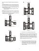
SUPPLY
AIR
RETURN
AIR
Temper ature Rise Meas ur eme nt
Figure 64
DIAGNOSTICS
Accessing the furnace’s diagnostic menu provides access to
the last six faults detected by the furnace. Faults are stored
most recent to least recent, Any consecutively repeated fault
is stored a maximum of three times. Example: A clogged
return air filter causes the furnace limit to trip repeatedly.
The control will only store this fault the first three consecu-
tive times the fault occurs.
NOTE: It is highly recommended that the fault history be
cleared when performing maintenance or servicing the
furnace.
N
ORMAL
S
EQUENCE
OF
O
PERATION
POWER UP
The normal power up sequence is as follows:
• 115 VAC power applied to furnace.
• Integrated control module performs internal checks.
• Integrated control module monitors safety circuits
continuously.
• The furnace enters a three minute power up delay
to make sure the system is setup properly. During
this time thermostat calls will not be recognized.
• Furnace awaits call from thermostat. 7-segment
LED’s display
Id L
while awaiting call from
thermostat.
HEATING MODE
The normal operational sequence in heating mode is as
follows:
• W thermostat contact closes, initiating a call for
heat.
• Integrated control module performs safety circuit
checks.
• Induced draft blower is energized on high speed for
a 15-second prepurge.