
Service Manual


26
When installed with a non-communicating thermostat, the
furnace integrated control module provides terminals for both
“W1” and “W2”, and “Y1” and “Y2” thermostat connections.
This allows the furnace to support the following system applica-
tions: ‘Two-Stage Heating Only’, ‘Two-Stage Heating with Single
Stage Cooling’, and ‘Two-Stage Heating with Two-Stage Cool-
ing’. Refer to the following figures for proper connections to
the integrated control module.
Low voltage connections can be made through either the right
or left side panel. Thermostat wiring entrance holes are located
in the blower compartment. The following figure shows connec-
tions for a “heat/cool system”.
This furnace is equipped with a 40 VA transformer to facilitate
use with most cooling equipment. Consult the wiring diagram,
located on the blower compartment door, for further details of
115 Volt and 24 Volt wiring.
NOTE: Use of ramping profiles requires a jumper between
Y1 and O when the outdoor unit is not a heat pump.
T
HERMOSTAT
“R”
REQUIRED
IF
OUTDOOR
UNIT
IS
EQUIPPED
WITH
A
C
OMFORT
A
LERT
™
MODULE
OR
IF
THE
OUTDOOR
UNIT
IS
A
PART
OF
THE
C
OMFORT
N
ET
™
FAMILY
OF
EQUIPMENT
.
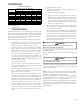
IMPORTANT NOTE
AUX
DEHUM
W2
C
1
Y1
2
R
W1
Y2
G
O
24 V THERMOSTAT CONNECTIONS
Low Voltage Connections with Auxiliary Terminals
The auxiliary contacts are shipped with a factory installed
jumper. As an option, the auxiliary contacts may be wired
to a normally closed float switch. In the event of open con-
tacts, the furnace will be disabled until the condition is cor-
rected. These are 24 volt terminals fed internally, do not
apply another voltage source to these terminals.
R
Y C
NEU
Furnace Integrated
Control Module
Remote
Condensing Unit
(Single-Stage Cooling)
Dehumidistat
[Optional]
R
Thermostat - Single-Stage Heating with Single-Stage Cooling
T
O
APPLY
A
SINGLE
-
STAGE
H
EATING
T
HERMOSTAT
,
THE
THERMOSTAT
SELECTOR
SWITCH
ON
THE
I
NTEGRATED
C
ONTROL
M
ODULE
MUST
BE
SET
ON
SINGLE
-
STAGE
.
IMPORTANT NOTE
_____________________________________
R
Y C
Furnace Integrated
Control Module
Remote
Condensing Unit
(Single-Stage Cooling)
Dehumidistat
[Optional]
NEU
R
Thermostat - Two-Stage Heating with Single-Stage Cooling
W1 W2
Y2
Furnace Integrated
Control Module
Remote
Condensing Unit
(Two-Stage Cooling)
Dehumidistat
[Optional]
Y2
NEU
W1 W2
Y2
Thermostat - Two-Stage Heating with Two-Stage Cooling
Thermostat Wiring Diagrams
S
ET
DIP
SWITCH
#14
TO
ON
POSITION
WHEN
USING
A
2-
STAGE
COOLING
THERMOSTAT
.
IMPORTANT NOTE
THERMOSTAT APPLICATION
The modulating furnace can be operated with a CTK01 com-
municating thermostat or a CTK02**, CTK03 or CTK04 com-
municating-modulating thermostat. It also facilitates op-
eration with a non-communicating single or two stage heat
/ cool thermostat.
NOTE: DIP switch #13 (Heating thermostat selection)must
be checked and set regardless of the thermostat chosen.
Factory setting is OFF (single stage), this is also the cor-
rect position if using CTK02**, CTK03 and CTK04 thermo-
stats. To use a CTK01 or a non-communicating two stage
thermostat, set the switch to the ON position.
Operation with CTK03 & CTK04
OPERATION