
Installation Guide


35
The integrated control will close the gas valve and
induced draft blower will be de-energized. The indoor
blower will shut down when the time delay expires
2. Remove the burner compartment door and move
position.
furnace.
4. Replace the burner compartment door.
The line pressure supplied to the gas valve must be within
-
installed in the gas piping drip leg. The supply pressure
must be measured with the burners operating. To measure
the gas supply pressure, use the following procedure.
valve external to the furnace.
pressure tap.
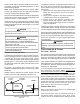
Outlet Pressure
Inlet Pressure
Regulator
Cover Screw
Connected to Manometer
the hose connection. If using the inlet pressure tap on the
3. Turn ON the gas supply and operate the furnace and all
other gas consuming appliances on the same gas supply
line.
Inlet Gas Supply Pressure table.
Natural 3.2 - 3.8" w.c. 3.5" w.c.
Propane 9.7 - 10.3" w.c. 10.0" w.c.
-
justments to pressure regulator, gas piping size, etc., and/or
consult with local gas utility.
disconnect manometer. Reinstall plug before turning on
gas to furnace.
6.
Only small variations in gas pressure should be made by adjusting
the gas valve pressure regulator. The manifold pressure must be
measured with the burners operating. To measure and adjust
the manifold pressure, use the following procedure.
external to the furnace.
3. Outlet pressure tap connections:
4. Attach a hose and manometer to the outlet pressure tap
5. Turn ON the gas supply.