
User's Manual


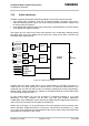


Table Of Contents
- Contents
- Figures
- Tables
- Document history
- Introduction
- Product concept
- GSM application interface
- GSM/GPRS operating modes
- Power supply
- Power up / down scenarios
- Automatic GPRS Multislot Class change
- Charging control of the GSM part
- Power saving
- Summary of state transitions (except SLEEP mode)
- RTC backup for GSM part of XT55/56
- Serial interfaces of the XT55/56 GSM part
- Audio interfaces
- SIM interface
- Control signals
- GPS application interface
- GSM and GPS antenna interfaces
- Electrical, reliability and radio characteristics
- Mechanics
- Reference approval
- Example applications
- List of parts and accessories

XT55/56 Hardware Interface Description
Confidential / Released
s
XT55/56_hd_v02.06a Page 56 of 125 17.12.2004
3.9.2 Features supported on the second serial interface of GSM
part (ASC1)
• 4-wire serial interface
• Includes only the data lines GSM_TXD1 and GSM_RXD1 plus GSM_RTS1 and
GSM_CTS1 for hardware handshake. This interface is intended for voice calls, GPRS
services and for controlling the GSM engine with AT commands. It is not suited for CSD
calls, fax calls and Multiplex mode.
• On ASC1 no GSM_RING line is available. The indication of URCs on the second
interface depends on the settings made with the AT^SCFG command. For details refer to
[1].
3.9.3 ASC0 and ASC1 configuration
• Both interfaces are configured for 8 data bits, no parity and 1 stop bit, and can be
operated at bit rates from 300bps to 230400 bps.
• XON/XOFF software flow control can be used on both interfaces (except if power saving
is active).
Table 13: DCE-DTE wiring of 1
st
serial interface (GSM part)
DCE (XT55/56) DTE (application) V.24
circuit
Pin function Signal direction Pin function Signal direction
103 GSM_TXD0 Input /TXD Output
104 GSM_RXD0 Output /RXD Input
105 GSM_RTS0 Input /RTS Output
106 GSM_CTS0 Output /CTS Input
108/2 GSM_DTR0 Input /DTR Output
107 GSM_DSR0 Output /DSR Input
109 GSM_DCD0 Output /DCD Input
125 GSM_RING0 Output /RING Input
Table 14: DCE-DTE wiring of 2
nd
serial interface (GSM part)
DCE (XT55/56) DTE (application) V.24
circuit
Pin function Signal direction Pin function Signal direction
103 GSM_TXD1 Input /TXD Output
104 GSM_RXD1 Output /RXD Input
105 GSM_RTS1 Input /RTS Output
106 GSM_CTS1 Output /CTS Input