
User's Manual


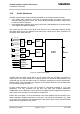


Table Of Contents
- Contents
- Figures
- Tables
- Document history
- Introduction
- Product concept
- GSM application interface
- GSM/GPRS operating modes
- Power supply
- Power up / down scenarios
- Automatic GPRS Multislot Class change
- Charging control of the GSM part
- Power saving
- Summary of state transitions (except SLEEP mode)
- RTC backup for GSM part of XT55/56
- Serial interfaces of the XT55/56 GSM part
- Audio interfaces
- SIM interface
- Control signals
- GPS application interface
- GSM and GPS antenna interfaces
- Electrical, reliability and radio characteristics
- Mechanics
- Reference approval
- Example applications
- List of parts and accessories

XT55/56 Hardware Interface Description
Confidential / Released
s
XT55/56_hd_v02.06a Page 54 of 125 17.12.2004
3.8 RTC backup for GSM part of XT55/56
The internal Real Time Clock of the XT55/56 GSM part is supplied from a separate voltage
regulator in the power supply ASIC which is also active when the GSM part of the XT55/56 is
in POWER DOWN status. An alarm function is provided that allows to wake up XT55/56
without logging on to the GSM network.
In addition, you can use the GSM_VDDLP pin on the board-to-board connector to backup the
RTC from an external capacitor or a battery (rechargeable or non-chargeable). The capacitor
is charged by the GSM_BATT+ line of XT55/56. If the voltage supply at GSM_BATT+ is
disconnected the RTC can be powered by the capacitor. The size of the capacitor
determines the duration of buffering when no voltage is applied to the GSM part of the
XT55/56, i.e. the greater capacitor the longer the GSM part of the XT55/56 will save the date
and time.
The following figures show various sample configurations. The voltage applied at
GSM_VDDLP can be in the range from 2 to 5.5V. Please refer to Table 27 for the
parameters required.
Baseband
processor
RTC
PSU
+
GSM_BATT+
1k
B2B
GSM_VDDLP
Figure 12: RTC supply from capacitor
RTC
PSU
+
GSM_BATT+
1k
B2B
GSM_VDDLP
Baseband
processor
Figure 13: RTC supply from rechargeable battery
RTC
PSU
+
+
GSM_BATT+
1k
GSM_VDDLP
B2B
Baseband
processor
Figure 14: RTC supply from non-chargeable battery