
User's Manual


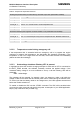


Table Of Contents
- Document history
- Introduction
- Product concept
- Application Interface
- Antenna interface
- Electrical, reliability and radio characteristics
- Mechanics
- Reference Approval
- Design example
- List of parts and accessories

MC55/56 Hardware Interface Description
Confidential / Preliminary
s
MC55/56_hd_v03.00 Page 38 of 104 16.08.2005
3.5 Charging control
MC55/56 integrates a charging management for Li-Ion batteries. You can skip this chapter if
charging is not your concern, or if you are not using the implemented charging algorithm.
MC55/56 has no on-board charging circuit. To benefit from the implemented charging
management you are required to install a charging circuit within your application. In this case,
MC55/56 needs to be powered from a Li-Ion battery pack, e.g. as specified in Table 8.
The module only delivers, via its POWER line and CHARGE line, the control signals needed
to start and stop the charging process. The charging circuit should include a transistor and
should be designed as illustrated in Figure 7. A list of parts recommended for the external
circuit is given in Table 7.
to BATT+
Input from
charger
(5.5V - 8V)
under load
CHARGE
470R
1SS355
3k3
100nF 10k
SI3441DV
4V3
1
/
5
ESDA6V1-5W6
to POWER
BATT_TEMP
1
/
5
ESDA6V1-5W6
NTC
+
Battery
pack
PCB spark
gap
CRS04
-
Figure 7: Schematic of approved charging transistor, trickle charging and ESD protection
Table 7: Bill of material for external charging circuit
Part Description First supplier Second supplier
SI3441DV
p-chan 2.5V (G-S) MOSFET
(TSOP-6)
VISHAY: SI3441DV-T1 NEC: UPA1911TE-T1
1SS355 100mA Si-diode (UMD2) ROHM: 1SS355TE-18 Toshiba: 1SS352TPH3
CRS04 1A Schottky diode Toshiba: CRS04 -
4V3
250mW; 200mA;
4.3V Z-Diode (SOD323)
Philips: PDZ4.3B
ROHM: UDZS4.3B
UDZ4.3B
ESDA6V1-5W6
ESD protection TRANSIL™
array
STM: ESDA6V1-5W6 -
470R, 3k3, 10k Resistor, e.g. 0805 or 0603 - -
100nF Ceramic capacitor 50V - -
PCB spark gap 0.2mm spark gap on PCB - -