GE Appliances Installation Instructions Built-In Dishwasher If you have questions, call 800.GE.CARES (800.432.2737) or visit our Website at: GEAppliances.com. In Canada, please call 1.800.561.3344 or visit www.geappliances.ca BEFORE YOU BEGIN Read these instructions completely and carefully. IMPORTANT – Observe all governing codes and ordinances. • Note to Installer – Be sure to leave these instructions for the consumer’s and local inspector’s use.
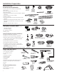
Installation Preparation PARTS SUPPLIED IN INSTALLATION PACKAGE: #10 Hose Clamp • Junction box cover and #10 hex-head screw Junction Hex-Head • Hose clamp Box Cover Junction Box Screw • Drain hose (approximately 78" long) 1/2" long • Drain hose hanger Drain Hose Hanger • 2 #8-18 hex head screws to secure brackets to washer tub frame • 1 top trim piece (on some models) Top Trim Piece (on some models) • 2 side trim pieces • 2 mounting brackets for wood countertops or side cabinets • 2 #8-18 x 5/8" Phillips s
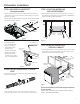
Installation Preparation PREPARE DISHWASHER ENCLOSURE WARNING: 7R UHGXFH WKH ULVN RI HOHFWULF VKRFN ¿UH RU LQMXU\ WR SHUVRQV WKH installer must ensure that the dishwasher is completely enclosed at the time of installation. + 1/4" 33-1/2” to 34-3/4” 34-1/2" Underside Underside ofof Countertop Countertop to Floor to Floor This Wall Area must be Free of Pipes or wires • The dishwasher must be installed so that drain hose is no more than 12' in length for proper drainage.
Installation Preparation PREPARE ELECTRICAL WIRING Alternate Receptacle Location WARNING: FOR PERSONAL SAFETY: Remove house fuse or open circuit breaker before beginning installation. Do not use an extension cord or adapter plug with this appliance. Electrical Requirements • This appliance must be supplied with 120V, 60 Hz., and connected to an individual properly grounded branch circuit, protected by a 15- or 20-ampere circuit breaker or time-delay fuse.
Installation Preparation PREPARE HOT WATER LINE NOTE: GE recommends copper tubing for the water line, but if \RX FKRRVH WR XVH ÀH[LEOH KRVH XVH *(·V WX28X326 ÀH[LEOH braided hose. CAUTION: Do not remove wood base until you are ready to install the dishwasher. The dishwasher will tip over when the door is opened if base is removed. • The water supply line (3/8” copper tubing or flexible braided hose) may enter from either side, rear or floor within the shaded area shown in Figure F.
Dishwasher Installation STEP 3: REMOVE WOOD BASE, INSTALL LEVELING LEGS STEP 1: PREPARATION Locate the items in the installation package: • Screws • Junction box cover • Drain hose and clamp • Mounting brackets • Trim pieces (on some models) • Drain hose hanger • Owner's Manual • Product samples and/or coupons IMPORTANT – 'R QRW NLFN RȺ ZRRG EDVH Damage will occur. • Move the dishwasher close to the installation location and lay it on its back.
Dishwasher Installation STEP 6: REMOVE FLOOR PROTECT (on some models) STEP 9: POSITION WATER LINE AND HOUSE WIRING • Remove leak sensor (on some models). Remove screw from leak sensor on the front of the Floor Protect with a 1/4" driver. • Remove 2 screws . • Rotate Floor Protect outward and lift out of the mounting tabs. • Set aside for use in Step 22. • Position water supply line and house wiring on the floor of the opening to avoid interference with base of dishwasher and components under dishwasher.
Dishwasher Installation STEP 11: SLIDE DISHWASHER THREE-FOURTHS OF THE WAY INTO CABINET STEP 13: INSTALL MOUNTING BRACKETS knees. Damage will occur. You must install the mounting brackets onto the dishwasher tub frame top or sides prior to sliding the dishwasher into place under the countertop. This dishwasher is capable of a true-flush installation at a 24” deep opening. The mounting brackets have several available attachment positions to accommodate different cabinet constructions.
Dishwasher Installation STEP 14: PUSH DISHWASHER INTO FINAL POSITION • Check the tub insulation blanket, if equipped, to be sure it is smoothly wrapped around the tub. It should not be “bunched up” and it must not interfere with the door springs. If the insulation is “bunched up” or interfering with the springs, straighten and recenter the blanket prior to sliding the dishwasher into its final position. • Slide the dishwasher into the final position by pushing on the sides of the door panel.
Dishwasher Installation STEP 16: POSITION DISHWASHER, SECURE TO COUNTERTOP OR CABINET STEP 17: CONNECT WATER SUPPLY Connect water supply line to 90° elbow. In this step you will need the 2 Phillips special head screws from the screws set aside in Step 1. The dishwasher must be secured to the countertop or the cabinet sides. When the underside of the countertop is wood, use Method 1. Use Method 2 when the underside of the countertop is made of a material, such as granite, that will not accept wood screws.
Dishwasher Installation STEP 18: CONNECT DRAIN LINE (Cont.) • Connect drain line to air gap, waste tee or disposer using the previously determined method. Secure hose with a screw-type clamp. Method 1 – Air gap with waste tee or disposer STEP 19: CONNECT POWER SUPPLY If a power cord with plug is already installed proceed to Step 20. WARNING: If house wiring is not 2-wire with ground, a ground must be provided by the installer.
Dishwasher Installation STEP 20: PRETEST CHECKLIST STEP 21: DISHWASHER WET TEST Review this list after installing your dishwasher to avoid charges for a service call that is not covered by your warranty. • Check to be sure power is OFF. • Turn on power supply or plug power cord into outlet, if equipped. • Open door and remove all foam and paper packaging. • Locate the Owner’s Manual set aside in Step 1. • Read the Owner’s Manual for operating instructions. • Check door opening and closing.
Dishwasher Installation Sound Barrier STEP 22: REPLACE FLOOR PROTECT (on some models) • Slide Floor Protect under dishwasher. • Angle the rear back edge of the Floor Protect upwards to engage mounting tabs. • Lift front of drip tray and secure with 2 screws. • Secure leak sensor to front of Floor Protect with 1 screw. Le ak se ns or STEP 24: REPLACE TOEKICK • Place toekick against the legs of the dishwasher.
Notes 14
Notes 15
SPECIFICATIONS SUBJECT TO CHANGE WITHOUT NOTICE GE Appliances General Electric Company Louisville, Kentucky 40225 GEAppliances.
Appareils ménagers GE Appliances Directives d’installation Lave-vaisselle encastré Pour toute question, composez le 1.800.561.3344 ou visitez notre site Web: www.electromenagersge.ca ARRÊT AVANT DE COMMENCER Veuillez lire attentivement toutes les directives qui suivent. IMPORTANT – Observez tous les codes et ordonnances en vigueur. • Note à l’installateur – Veuillez laisser les présentes directives au consommateur pour l’inspecteur local.
Préparation pour l’installation PIÈCES FOURNIES DANS L’EMBALLAGE: • Couvercle de la boîte de jonction et vis à tête hexagonale n° 10 Vis à tête Couvercle de la • Collier hexagonale n° 10 boîte de jonction • Boyau de vidange (198 cm/78 po de long) de 12,7 mm (1/2 po) et vis à tête • Support de tuyau de vidange de long pour boîte hexagonale n° 10 de jonction • 2 Vis à tête hexagonale no 8-18 pour fixer les supports au cadre de la cuve du lave-vaisselle • 2 Boutons de bouchon Garniture (supérieure) • 2 Moulure
Préparation pour l’installation PRÉPARATION DE L’OUVERTURE DANS LES ARMOIRES Le mur du fond doit être exempt de tuyaux ou de fils 33-1/2 po to 34-3/4 po du dessous du comptoir au plancher • Le lave-vaisselle doit être installé de façon à ce que le boyau de vidange mesure au maximum 3.66 mètres (12 pieds) pour assurer une vidange adéquate. • Le dessus, les côtés et l’arrière du lave-vaisselle doivent être complètement dissimulés à l’intérieur de l’ouverture.
Préparation pour l’installation PRÉPARATION DU CÂBLAGE ÉLECTRIQUE Autre emplacement possible pour la prise de courant AVERTISSEMENT: POUR VOTRE SÉCURITÉ PERSONNELLE: Enlevez le fusible ou déclenchez le disjoncteur au panneau de distribution principal avant de commencer l’installation.
Préparation pour l’installation PRÉPARATION DE L’ALIMENTATION EN EAU CHAUDE REMARQUE: GE recommande l’utilisation d’un tuyau en cuivre pour la conduite d’alimentation en eau, mais vous pouvez choiVLU XQ ER\DX ÀH[LEOH WUHVVp QR WX28X326 de GE. • La conduite d’alimentation en eau (tuyau de cuivre de 9,5 mm [3/8 po] ou boyau flexible tressé) peut entrer du côté gauche, du côté droit, de l’arrière ou du plancher dans la partie ombrée indiquée dans la Figure F.
Installation du lave-vaisselle ÉTAPE 1: PRÉPARATION Prenez les pièces fournies dans l’emballage et mettez-les de côté: • Ensemble de vis • Couvercle de la boîte de jonction • Boyau de vidange et collier • Supports de montage • Moulures (certains modèles) • Crochet pour boyau de vidange • Manuel d’utilisation • Échantillons et(ou) bons ÉTAPE 2: VÉRIFICATION DE L’ÉQUILIBRE DE LA PORTE La porte se REMARQUE : Si vous installez un panneau personnalisé referme àl'intérieur RȺHUW VXU FHUWDLQV PRGqOHV de 20°
Installation du lave-vaisselle ÉTAPE 5: INSTALLATION DU MATÉRIAU INSONORISANT (sur certains modèles) Passez à l'étape suivant si le lave-vaisselle n'est pas équipé de matériau insonorisant Relevez le matériau insonorisant et le ruban et fixez-le au panneau frontal à l'aide du ruban-cache. Ceci permettra de garder le matériau insonorisant relevé et de dégager la zone de travail pendant l'installation.
Installation du lave-vaisselle ÉTAPE 11: INSERTION AUX TROIS QUARTS DU LAVE-VAISSELLE DANS L’OUVERTURE IMPORTANT – Ne poussez pas sur le panneau avant avec vos genoux. Vous pourriez endommager l’appareil. • Saisissez le panneau avant de l’appareil par les côtés et faites glisser le lave-vaisselle dans l’ouverture de quelques centimètres ou pouces à la fois.
Installation du lave-vaisselle ÉTAPE 14: INSTLLATION DU LAVEVAISSELLE DANS SON EMPLACEMENT DÉFINITIF • Vérifiez l’isolant de la cuve, s’il y a lieu, pour vous assurer qu’il enveloppe complètement la cuve. L’isolant ne doit pas «retrousser» ou entrer en contact avec les ressorts de la porte. Si l’isolant est «déplacé» ou entre en contact avec les ressorts, replacez-le correctement avant de faire glisser l’appareil dans son emplacement définitif.
Installation du lave-vaisselle ÉTAPE 16: FIXATION DU LAVE-VAISSELLE AUDESSOUS DU COMPTOIR OU AUX CÔTÉS DES ARMOIRES ÉTAPE 17: RACCORDEMENT DE L’ALIMENTATION EN EAU Au cours de cette étape, vous aurez besoin des deux vis à tête spéciale Phillips mises de côté à l’étape 1. Le lave-vaisselle doit être fixé au dessous du comptoir ou aux côtés des armoires. Lorsque le dessous du comptoir est en bois, utilisez la méthode n° 1.
Installation du lave-vaisselle ÉTAPE 18: RACCORDEMENT DU BOYAU DE VIDANGE L’extrémité moulée du boyau de vidange est conçue pour s’installer sur l’orifice d’entrée d’un diamètre variant entre 15,8 mm (5/8 po) et 25,4 mm (1 po) de la coupure anti-refoulement, du raccord en T ou du broyeur à déchets. 0HVXUH] OH GLDPqWUH GH O·RUL¿FH G·HQWUpH • Coupez le raccord du Ligne de coupe boyau de vidange à l’endroit indiqué, 15,8 mm (5/8 po) au besoin, pour qu’il soit bien DGDSWp j O·RUL¿FH d’entrée.
Installation du lave-vaisselle ÉTAPE 19: BRANCHEMENT DE L’ALIMENTATION ÉLECTRIQUE ÉTAPE 20: LISTE DE CONTRÔLE PRÉLIMINAIRE Si un cordon d’alimentation pourvu d’une fiche est déjà installé sur l’appareil, passez à l’étape 20. Passez en revue cette liste après l’installation de votre lave-vaisselle pour éviter des frais de réparation inutiles non couverts par votre garantie.
Installation du lave-vaisselle ÉTAPE 21: ESSAI DU LAVE-VAISSELLE AVEC DE L’EAU ÉTAPE 22: INSTALLATION DU PROTÈGEPLANCHER (sur certains modèles) • Rétablissez l’alimentation électrique ou si l’appareil est doté d’un cordon d’alimentation, branchez-le dans la prise de courant murale. • Faites glisser le protège-plancher sous le lave-vaisselle. • Angle the rear back edge of the Floor Protect upwards to engage mounting tabs. • Soulevez le devant du plateau et sécurisez avec les 2 vis.
Installation du lave-vaisselle ÉTAPE 23 : INSTALLATION DU MATÉRIAU INSONORISANT ET DU MATÉRIAU ISOLANT (sur certains modèles) Passez à l'étape suivant si le lave-vaisselle n'est pas équipé de matériau insonorisant. • Repérez l'emballage du matériau isolant à l'intérieur du lavevaisselle. • Repérer la boîte de commande. Boîte de ÉTAPE 24: RÉINSTALLATION DU PANNEAU INFÉRIEUR • Appuyez le panneau inférieur contre les pieds de nivellement du lave-vaisselle.
Notes 15
LES SPÉCIFICATIONS PEUVENT ÊTRE MODIFIÉES SANS PRÉAVIS GE Appliances General Electric Company Louisville, Kentucky 40225 www.electromenagersge.
GE Appliances Instrucciones de Instalación Lavavajillas Incorporado Ante cualquier duda, comuníquese al 800.GE.CARES (800.432.2737) o visite nuestro sitio web en: GEAppliances.com. En Canadá, comuníquese al 1.800.561.3344 o visite www.geappliances.ca. ALTO ANTES DE COMENZAR Lea estas instrucciones en su totalidad y atentamente. IMPORTANTE – Cumpla con todos los códigos y ordenanzas gubernamentales • Nota para el Instalador – Asegúrese de entregar estas instrucciones al consumidor y al inspector local.
Preparación de la Instalación PIEZAS SUMINISTRADAS EN EL PAQUETE DE INSTALACIÓN: • Tapa de la caja de empalmes y tornillo de cabeza hexagonal nº 10 • Abrazadera de la manguera • Manguera de desagüe (aprox.
Preparación de la Instalación PREPARE EL AMURADO DEL LAVAVAJILLAS ADVERTENCIA: Para reducir el riesgo de descarga eléctrica, incendio o lesiones a personas, el instalador debe asegurarse de que el lavaplatos esté completamente cerrado en el momento de la instalación.
Preparación de la Instalación PREPARACIÓN DEL CABLEADO ELÉCTRICO Ubicación de ADVERTENCIA: PARA SEGURIDAD PERSONAL: Quite el fusible o abra el Ubicación de receptáculo receptáculo alternativo alternativo interruptor de circuitos antes de comenzar la instalación. No utilice un cable de extensión o un enchufe adaptador con este artefacto.
Preparación de la Instalación PREPARACIÓN DE LA LÍNEA DE AGUA CALIENTE NOTA: GE recomienda el uso de tuberías de cobre para la línea de agua, pero si decide usar una manguera flexible, use la manguera trenzada flexible WX28X326 de GE. PRECAUCIÓN: No quite la base de madera hasta que esté listo para instalar el lavaplatos. Si se quita la base, el lavaplatos se volcará cuando se abra la puerta.
Instalación del Lavavajillas PASO 3: RETIRE LA BASE DE MADERA, INSTALE LAS PATAS NIVELADORAS PASO 1: PREPARACIÓN Ubique los ítems en el paquete de instalación: • Tornillos • Tapa de la caja de empalmes • Manguera de desagüe y clavija • Soportes de montaje • Pieza de los bordes (en algunos modelos • Gancho de la manguera de desagüe • Manual del propietario • Textos, muestras y/o cupones IMPORTANTE – ¡No patee la base de madera! Se producirán daños.
Instalación del Lavavajillas PASO 6: RETIRE LA PROTECCIÓN DEL PISO (en algunos modelos) PASO 9: POSICIONE LA LÍNEA DE AGUA Y EL CABLEADO DE LA CASA • Retire el sensor de goteos (en algunos modelos). Retire el tornillo del sensor de pérdidas en el frente de la Protección del Piso con un destornillador de ¼”. • Retire los 2 tornillos. • Gire la protección del piso hacia afuera y levante la misma de las lengüetas de montaje. • Deje a un costado para uso en el Paso 22.
Instalación del Lavavajillas PASO 11: DESLICE EL LAVAVAJILLAS TRES CUARTOS DEL RECORRIDO DENTRO DEL GABINETE IMPORTANTE – No lo empuje contra el panel frontal con las rodillas. Se producirán daños. • Tome los laterales del panel frontal y deslice el lavavajillas en la abertura de a pocas pulgadas por vez. No lo empuje contra el panel de la puerta frontal con la rodilla. Se poducirán daños sobre el panel de la puerta.
Instalación del Lavavajillas PASO 14: COLOQUE EL LAVAVAJILLAS EN SU POSICIÓN FINAL • Controle que la manta aislante, si está presente, esté envuelta de forma pareja alrededor de la tubería. No debería estar “amontonada” y no debe interferir con los resortes de la puerta. Si el aislante está “amontonado” o interfiere con los resortes, alargue y vuelva a centrar la manta antes de deslizar el lavavajillas hasta su posición final.
Instalación del Lavavajillas PASO 15: NIVELE EL LAVAVAJILLAS IMPORTANTE – El lavavajillas deberá estar nivelado para un funcionamiento apropiado del estante de los platos, el rendimiento del lavado y el funcionamiento de la puerta. El lavavajillas deberá estar nivelado de izquierda a derecha y del frente a la parte trasera.
Instalación del Lavavajillas PASO 16: POSICIONE EL LAVAVAJILLAS, ASEGURE EL MISMO A LA MESADA O EL GABINETE En este paso, necesitará los 2 tornillos con cabeza especial Phillips, de los tornillos que separó en el Paso 1. El lavavajillas deberá estar asegurado a la mesada o a los costados del gabinete. Cuando el lado inferior de la mesada sea de madera, use el Método 1. Use el Método 2 cuando el lado inferior de la mesada esté hecho de un material que no acepte tornillos de madera, tal como el granito.
Instalación del Lavavajillas PASO 18: CONECTE LA LÍNEA DE DESAGÜE (Cont.) • Conecte la línea de desagüe a la brecha de aire, la T de desechos o el eliminador de desechos, usando el método determinado previamente. Asegure la manguera con una clavija tipo tornillo. Método 1 – Brecha de aire con T de desechos o el eliminador de desechos PASO 19: CONECTE EL SUMINISTRO DE CORRIENTE Si un cable de corriente con un enchufe ya está instalado, proceda al Paso 20.
Instalación del Lavavajillas PASO 20: LISTA DE CONTROL DE EVALUACIÓN PREVIA PASO 21: PRUEBA DE MOJADO DEL LAVAVAJILLAS Revise esta lista luego de instalar el lavavajillas, a fin de evitar cargos por llamadas al servicio técnico, las cuales no están cubiertas por su garantía. • Active la corriente y enchufe el cable de corriente en el tomacorriente, si está equipado de este modo. • Asegúrese de que el encendido esté en OFF (Apagado). • Asegúrese de que la puerta esté trabada.
Instalación del Lavavajillas PASO 22: REEMPLACE LA PROTECCIÓN PARA PISOS (en algunos modelos) Barrera de sonido • Deslice la Protección para Pisos debajo del lavavajillas. • Coloque en ángulo el extremo inferior de la Protección para Pisos hacia arriba, para adherir las lengüetas de montaje. • Levante el frente de la bandeja de goteo y asegure la misma con 2 tornillos. • Asegure el sensor de pérdidas sobre el frente de la Protección para Pisos con 1 tornillo.
Notas 15
ESPECIFICACIONES SUJETAS A CAMBIOS SIN AVISO PREVIO GE Appliances General Electric Company Louisville, Kentucky 40225 GEAppliances.