
User's Manual


72 MDS Master Station MDS 05-6399A01, Rev. D
6.3.7 GPS Antenna Interface (Optional)
Integrated GPS is a future option.
6.4 SD Master Radio Modules
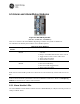
Figure 6-7. SD Radio Module
(Part No. 03-6846Axx—SDM9)
The SD Master Radio Modules are field replaceable, hot swappable, full duplex radios offering narrow-
band communications. Current offerings include variants that span 800-960MHz.
NOTE: Master station Radio modules are field replaceable and hot swappable. Refer to 7.4 Replacing
Modules for information on removal and installation.
NOTE: When installing Radio Modules, torque thumbscrews to 10 in-lbs to insure optimum heat transfer
through thermal contact connector on the rear of the unit.
6.4.1 SD Master Radio Module LED Indicators
The SD Radio Modules have bi-color green/red LEDs to indicate power, alarm, and active/standby status
as shown in the table below. Blue LEDs to indicate receiver transmit and receive are also provided.
Table 6-11. SD Radio Module LEDs
LED Name Behavio
r
Meaning
PWR/ALARM
GREEN
FLASHING RED
FLASHING GREEN
Alternating with ACTIVE
Power applied
Alarmed radio
Radio power-up
Firmware is updating
ACTIVE
GREEN
OFF
Alternating with PWR
Active
Standby
Firmware is updating
TX BLUE Transmitting
RX BLUE Receiving
6.4.2 SD Master Radio Module RF Interface
SD Radio Modules include keyed RF Connectors for front connection to either an Alarm/Relay Module,
if used in a redundant system, or to the front of the duplexer tray if used in a non-redundant system.
Different cables are used in each case. Systems assembled by the factory come pre-wired using the