
User's Manual


MDS 05-6399A01, Rev. D MDS Master Station 71
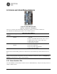
Table 6-8 COM2 Pin Descriptions—Radio in RS-485 Mode
Pin
Number
Input/
Output
Pin Description
1 --
Reserved—Do not connect
2 --
Reserved—Do not connect
3 --
Reserved—Do not connect
4 -
Ground—Connects to ground (negative supply potential) on
the radio’s PC board.
5 IN
TXD+/TXB (Transmitted Data +)— Non-inverting receiver
input
6 OUT
RXD+/RXB (Received Data +)—Non-inverting driver output.
7 IN
TXD-/TXA (Transmitted Data -)— Inverting receiver input
8 OUT
RXD-/RXA (Received Data -)— Inverting driver output.
COM2 RS-485 and RS-422 Wiring Arrangement
• RXD+ / RXB and RXD– / RXA are data received by the radio and transmitted
• RXD+ / RXB is positive with respect to RXD– / RXA when the line input is a “0”
• TXD+ / TXB and TXD– / TXA are data sent to the radio to be transmitted
• TXD+ / TXB is positive with respect to the TXD– / TXA when the line output is a “0”
Table 6-9 EIA-422 4-Wire Connections
External DB-9 COM2
TXD- 2 7 TXD-
RXD- 3 8 RXD-
RXD+ 7 6 RXD+
TXD+ 8 5 TRD+
Table 6-10 EIA-485 2-Wire Connections
External DB-9 COM2
TXD- 2
RXD-/TXD-
RXD- 3
RXD+ 7
RXD+/TXD+
TXD+ 8
6.3.5 Mini USB Interface
The USB Interface follows standard Mini-USB wiring and protocol. This interface can be used to access a
command line user interface when connected to a computer USB port and the GE provided driver is
installed. Refer to 3.6.3 Mini USB for more information.
6.3.6 Wifi Antenna Interface (Optional)
Integrated Wifi is a future option.