
User's Manual


2. WIRING
2-25
2.5 Monitor Unit
For the wiring of the monitor unit, see the operator’s manual supplied with the monitor
unit.
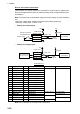
Installation considerations
<Standard type>
• Connect the main monitor to the DVI1 and COM1 ports.
• For the sub monitor, connect it to the DVI2 and COM2 port.
<VDR connection, ask your dealer>
To connect a VDR, it is necessary to output data in analog format. See the installation
manuals for VDR to prepare the cables to use.
• When connecting a VDR to the DVI3 port:
Use the optional DVI-BNCX5-L2000 cable to output RGB signal from the DVI-I. Ad-
justment of the output picture is necessary.
• When connecting a VDR to the DVI2 port:
Use a DVI/RGB converter (maker: IMAGENICS, type: DVI-12A, local supply) to
convert DVI output from DVI2 port to RGB.
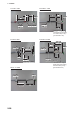
Menu setting
The [INSTALLATION SETTING] menu appears only when the power is turned on for
the first time after installation of the monitor unit.
Adjust the settings referring to the following table.
*: [DVI PWR SYNC] is the slide switch at the bottom rear of the monitor unit. Confirm
that this switch is set to [ON] (default setting). See Slide switch below for details.
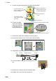
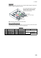
Slide switch
Set the slide switch to “ON”
(default setting). This setting
automatically powers the mon-
itor unit on or off according to
the DVI signal input. The pow-
er switch of the monitor unit is
inoperative.
Note: The OFF position provides control of the monitor unit power with the power
switch of the monitor unit.
EXT BRILL
CTRL
SERIAL
BAUDRATE
COLOR
CALIBRATION
KEY LOCK
DVI PWR
SYNC*
RS-485 4800bps ON ON ON
INSTALLATION SETTING
EXT BRILL CTRL
SERIAL BAUDRATE
COLOR CALIBRATION
KEY LOCK
SAVE AND EXIT
RS-485
4800bps
ON
ON
YES
(OFF/DVI1/DVI2/RS-232C/RS-485/USB)
(4800/9600/19200/38400)
(OFF/ON)
(OFF/ON)
(NO/YES)
Menu
Menu item
Slide switch
ON (Default setting)
DVI
port
OFF
RGB
port