
Installation guide


Contents
SUBJECT PAGE
Pre-lnstallation Requirements .......................................... 2
Electrical Requirements ................................................... 2
Water Supply Requirements ........................................... 2
Drain Requirements .......................................................... 2
Exhaust System Requirements ...................................... 2-3
Gas Supply Requirements ................................................ 3
Location ............................................................................ 3
Mobile Home Installation .................................................. 3
Rough-In Dimensions ......................................................... 4
Unpacking ......................................................................... 4
Electrical Installation ......................................................... 5
Grounding Requirements .................................................. 5
3 & 4-Wire Connections ................................................. 5-6
installation ..................................................................... 6-7
Replacement Parts ........................................................... 7
PRE-INSTALLATION REQUIREMENTS
Tools and Materials Required for Installation:
1. Phillips head screwdriver.
2. Channel-lock adjustable pliers.
3. Carpenter's level.
4. Flat or straight blade screwdriver.
5. Duct tape.
6. Rigid or flexible metal 4 inch (10.16 cm) duct.
7. Vent hood.
8. Pipe thread sealer (Gas).
9. Ratchet with 3/8 inch (0.96 cm) socket.
For your safety the information in this manual must be
followed to minimize the risk of fire or explosion or to prevent property
damage, personal injury or loss of life.
- Do not store or use gasoline or other flammable vapors and
liquid in the vicinity of this or any other appliance.
- WHAT TO DO IF YOU SMELL GAS
• Do not try to light any appliance.
. Do not touch any electrical switch; do not use any phone in your
buikJing.
• Clear the room, building or area of all occupants.
Immediately call your gas supplier from a neighbor_ phone.
• Follow the gas supplier's instructions.
• If you cannot reach your gas supplier, call the fire department.
Installation and service must be preformed by a qualified installer, service
agency or the gas supplier.
ELECTRICAL REQUIREMENTS
[ ELECrR/CLaundry Center ]
Circuit- Individual 30 amp branch circuit fused with 30 amp minimum time
delay fuses or circuit breakers.
POWER SUPPLY - 3-wire or 4-wire , 240 volt, single phase, 60 Hz,
Alternating Current.
POWER SUPPLY CORD KIT- The laundry center MUST employ a 3-
condutor power supply cord NEMA 10-30 type SRDT rated at 240 volt AC
minimum, 30 amp, with 3 open end spade lug connectors with upturned
ends or closed loop connector OR a 4-condutor power supply cord NEMA
14-30 type SRDT or ST (as required) rated at 240 volt AC minimum, 30
amp, with 4 open end spade lug connectors with upturned ends or closed
loop connectors and marked for use with clothes dryers, if being installed
in a new branch circuit installation, manufactured (mobile) home, recreational
vehicle or area which prohibits grounding through the neutral conductor,
the laundry center MUST employ a 4-condutor power supply cord NEMA
14- 30 type SRDT or ST (as required) rated at 240 volt AC minimum, 30
amp, with 4 open end spade lug connectors with upturned ends or closed
loop connectors and marked for use with clothes dryers. See ELECTRICAL
CONNECTIONS. (Canada - 4-wire power supply cord is installed on laundry
center.)
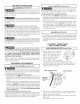
OUTLET RECEPTACLE- NEMA 10-30R (3-wire) receptacle or NEMA 14-
30R (4-wire) receptacle to be located so the power supply cord is accessible
when the laundry center is in an installed position.
NEMA NEMA
I GASLaundry Center ]
CIRCUIT- Individual 15 amp
minimum branch circuit fused with NOTE:Donot under
anycircumstances
a time delay fuse or circuit reroovegrounding
break er. prongfromplug.
POWER SUPPLY -3 wire, 120
volt single phase, 60 Hz,
Alternating Current.
POWER SUPPLY CORD -The
gas laundry center is equipped
with a 120 volt 3-wire power
cord. GroundingProng
WATER SUPPLY REQUIREMENTS
Hot and cold water faucets MUST be installed within 42 inches (106.68
cm) of your laundry center's water inlet. The faucets MUST be 3/4 inch
(1.9 cm) garden hose type so inlet hoses can be connected. Water
pressure MUSTbe between 10 and 120 pounds per square inch (maximum
unbalance pressure, hot vs. cold, 10 psi). Your water department can
advise you of your water pressure.
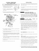
DRAIN REQUIREMENTS
1. Drain capable of
eliminating 17 gaB. per
minute.
2. A standpipe diameter of
I_A inches (3.18 cm)
minimum.
3. The standpipe height
above the floor should
be:
Minimum height:
33 inches (83.82 cm)
Maximum height:
96 inches (244 cm)
33" Min.
(83.82cm)
1'
96"Max.
(244 cm)
NOTE: For installations requiring a longer drain hose, have a qualified
technician install a longer hose, PIN 134049201, available from an authorized
parts distributor. For drain systems in the floor, install a siphon break kit,
available from your local hardware store .
EXHAUST SYSTEM REQUIREMENTS
Use only 4 inch (10.16 cm) diameter (minimum) Hqid or flexible
metal duct and approved vent hood which has a swing-out
damper(s) that opens when the dryer is in operation. When the
dryer stops, the damper(s) automatically closes to prevent drafts
and the entrance of insects and rodents. To avoid restricting the
outlet, maintain a minimum of 12 inches (38.5 cm) clearance
between the vent hood and the ground or any other obstruction.
_The following are specific requirements for proper and
safe operation of your laundry center. Failure to follow these instructions
can create excessive drying times and fire hazards.
Do not use plastic flexible duct or metal foil to exhaust
the dryer. Excessive lint can build up inside the exhaust system and create
a fire hazard and restrict air flow. Restricted air flow will increase drying
times. If your present system is made up of plastic duct or metal foil duct,
_lace it with a rigid or flexible metal duct. Ensure the present duct is
free of any lint prior to installing laundry center dryer duct.
_lf the dryer is not exhausted outdoors some fine lint will
be expelled into the laundry area. An accumulation of lint in any area of
the home can create a health and fire hazard. The dryer exhaust system
MUST be exhausted to the outside of the dwelling!
Do not allow combustible materials (for example:
dothinq,draperies/curtains, paper) to come in contact with the exhaust
_stem. The dryer MUST NOT be exhausted into a chimney, a wall, a
ceiling, or any concealed space of a building which can accumulate lint,
resulting in a fire hazard.
Do not exceed the length of duct pipe or number of
elbows allowed in the" EXHAUST DUCT LENGTHS" chart. Lint can
accumulate in the system, plugging the system and creating a fire hazard,
as well as increasing drying times.
_Do not screen the exhaust ends of the vent system nor
use any screws or rivets to assemble the exhaust system. Lint can
become caught in the screen, on the screws or rivets, clogging the
exhaust system and creating a fire hazard as well as increasing drying
times. Use an approved vent hood to terminate the duct outdoors, and
seal all joints with duct tape. All male duct pipe fittings MUST be installed
downstream with the flow of air.