
Parts List


- 11 -
FUSE
FUSE
FUSE
1
2
9
5
12
11
14
15
16
18
19
10
17
21
FUSE
FUSE
FUSE
4
6
7
8
20
3
13
22
1
2
3
4
4
4
.
.
1
1
.
.
3
3
A
A
l
l
p
p
h
h
a
a
6
6
0
0
7
7
/
/
6
6
0
0
8
8
I
I
n
n
t
t
e
e
r
r
n
n
a
a
l
l
A
A
s
s
s
s
e
e
m
m
b
b
l
l
y
y
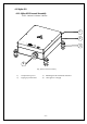
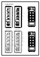
(Fig. 8) Internal Parts Assembly
(1) Spare fuse & jumper compartment
(2) Spare Jumper slots
(3) Spare fuse slots
(4) Receiver top casing
1) Receiving RF module
2) External programming port
3) Power module
4) Secondary power AC fuse (F1)
5) Contact output seat (CN8)
6) Primary power AC fuse (FF1)
7) AC power input seat (CN2)
8) Internal Antenna
9) System Status LED display*
10 )External antenna port
11) ID code dip-switch
12) Receiving RF module red status light
13) Transmitter pairing button
14) Contact relay LED display
15) Pushbutton #1and #2 fuse (5.0A)
16) Contact output seat (CN3)
17) MAIN contact fuse F6 (5.0A)
18) Pushbutton #3 and #4 fuse F4 (5.0A)
19) Pushbutton #5 and #6 fuse F3 (5.0A)
20) Contact output seat (CN4)
21) AUX1/AUX2/LV /I/II fuse F5(5.0A)
22) Cable gland & output cable
* Power module: Including transformer or
full-voltage module.
* Please refer to 4.3 α604/α608/α612 Receiver
Power Fuse List.
*Please refer to page 37 for system status
LED display information.