
User Manual


- 6 -
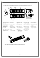
4.2.3 Encoder Board, TX Module, Recharging chip card and Rechargeable Battery Descriptions:
(Fig. 3) Encoder Board, RF Module, Power Card Descriptions
1.Transmitting channel
dip-switch
5. Start Switch
9.LED Display cable
port
13.Transmitting RF
module cable port
17.Chip Card Holder
2. Adjustable capacitor
for PLL frequency
compensation
6. One/Two speed
pushbutton
10.AUX dip-switch 14. ID code dip-switch 18.Battery pack contact
spring
3.Transmitting RF
module cable
7. Emergency Stop
Pushbutton (EMS)
11.Micro-Processor
Programming Port
15.Battery charging
board to encoder
board cable port
19.Battery charging
wiring loop holder
4.Port of Encoder board
to battery charging
board port
8. Power
Switch(ON/OFF)
12.Extra 2 aux.
pushbuttons and
selector switch
cable connector
16.Chip card special
setting port
(Fig. 4) Encoder Board, TX Module and Power Card Interior Descriptions