
User Manual


9
RECEIVER INSTALLATION/SERVO CONNECTIONS (CONTINUED)
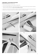
Connecting a traditional receiver to Aura with PWM Servo Connections
PWM is an acronym which stands for Pulse Width Modulation. A servo will move to a specic angle in a specic direction based on the width of
the signal pulse it receives. Most transmitters output a total pulse width of 1.1-1.9ms, with the midpoint being 1.5ms. Lower pulse widths will
move the servo to one side of neutral and higher pulse widths to the other side of neutral. In order to utilize this type of receiver connection
with your Mamba 10, male to male servo leads to connect the corresponding receiver ports to Aura are required. A minimum 6-channel receiver
is required to setup Aura with PWM connections. Please purchase FPZAU01 Aura 3-piece male to male servo cable/S.Bus to complete the
PWM connection setup.
1. Bind your receiver to your transmitter by following the instructions provided by your transmitter and receiver manufacturer. Verify that it is
bound by connecting a spare servo to the receiver and verify that it responds to the appropriate input.
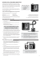
2. With the transmitter and receiver powered OFF, connect your receiver to Aura using the diagram below. Note that the throttle is plugged
directly into the receiver.
3. With the propeller removed and ALL connections made between Aura and the receiver (observing correct polarity), power on your
transmitter and the airplane with the ight battery, ensuring that the airplane is kept stationary. After a few seconds, the LEDs on Aura will
sweep back and forth as Aura searches for a valid control signal. Once found, a solid orange (Aura running) and solid green (Aura receiving
valid signal from the receiver) LED is illuminated. After the source is found, apply transmitter right rudder to assist Aura determine
your radio type, after which point control of the model is established. This is only required during initial setup.
NOTICE
VERIFY PROPER POLARITY OF ALL CABLE CONNECTIONS PRIOR TO ADDING POWER TO THE SYSTEM
All four (4) PWM male-to-male connections must be connected AND connected in the proper polarity from receiver
outputs to Aura inputs for Aura to activate servo outputs. (Aileron - S1, Elevator - S2, Rudder - S3, Gear/CH5 - S4)
CAUTION
Always connect the battery when the throttle stick and
throttle trim are in the idle/cut-o position.
Observe the following procedures to safely power up your
model after it has been bound. Ensure propeller is removed
unless sequence is followed to power up before ight.
1. Lower the throttle stick and trim to their lowest setting
and turn on the transmitter. Wait for your transmitter to
indicate the RF signal is being broadcast before proceeding.
If a battery is connected to the ESC with the throttle fully
open on the active transmitter, the ESC will enter into
programming mode. If this occurs, simply disconnect the
battery, lower the throttle, and reconnect the battery.
2. Ensure the rudder, elevator, and aileron gimbals are centered.
3. With the airplane on a solid surface; connect the battery
to the ESC and wait. The ESC will emit a series of audible
tones during its initialization process.
4. The ESC will emit a short, nal tone sequence indicating
that the ESC is now armed, and that the motor will spin in
responose to throttle stick movement.
CONNECTING BATTERY/ARMING ESC
WARNING
When making adjustments to linkages, transmitter
settings, or the Aura 8 ight control system, remove the
propeller to guard against accidental spool up.
WARNING
Hold aircraft securely when connecting the battery before
ight. Always ensure that the propeller is clear of any and all
objects as they may become entangled.
Receiver PWM Inputs
THROTTLE
AILERON
ELEVATOR
RUDDER
GEAR/CH5
AUX1/CH6
RX
RUDDER SERVO
ELEVATOR SERVO
RIGHT WING AILERON SERVOS
LEFT WING AILERON SERVOS
ESC
To Motor
To RX
Servo PWM Outputs
*Note: Arrows indicate signal (data) ow.They
do not necessarily indicate voltage (+) ow.