
Data Sheet


VII-2018, www.findernet.com
5
A
56
SERIES
56 SERIES
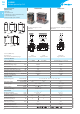
Miniature power relays 12A
Ordering information
Example: 56 series plug-in relay, 2 CO (DPDT), 12VDC coil, lockable test button and mechanical indicator.
A B C D
5 6 . 3 2 . 9 . 0 1 2 . 0 0 4 0
Series
Type
3 = Plug-in
4 = PCB
No. of poles
2 = 2 pole, 12A
4 = 4 pole, 12A
Coil version
8 = AC (50/60Hz)
9 = DC
Coil voltage
See coil specifications
A: Contact material
0 = Standard AgNi
2 = AgCdO
4 = AgSnO
2
B: Contact circuit
0 = CO (nPDT)
3 = NO (nPST), ≥1.5mm
contact gap
D: Special versions
0 = Standard
1 = Wash tight (RTIII) for 56.42 and
56.44 only
6 = Rear flange mount (4 pole only)
8 = Rear 35mm rail mount (4 pole
only)
For other mounting options see page 8
C: Options
0 = None
2 = Mechanical indicator
3* = LED (AC)
4 = Lockable test button +
mechanical indicator
5* = Lockable test button + LED (AC)
54* = Lockable test button + LED (AC) +
mechanical indicator
6* = Double LED (DC non-polarized)
7* = Lockable test button + double
LED (DC non-polarized)
74* = Lockable test button + double
LED (DC non-polarized) +
mechanical indicator
8* = LED + diode (DC, polarity positive
to pin 7) for 56.32 only
9* = Lockable test button + LED +
diode (DC, polarity positive to pin
7) for 56.32 only
94* = Lockable test button + LED +
diode (DC, polarity positive to
pin 7) + mechanical indicator for
56.32 only
* Options not available for 220VDC and
400VAC versions.
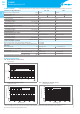
Selecting features and options: only combinations in the same row are possible.
Preferred selections for best availability are shown in bold.
Type Coil version A B C D
56.32
AC 0 - 2 - 4 0 0 - 2 - 3 - 4 - 5 0
AC 0 - 2 - 4 0 54 /
AC 0 - 2 - 4 3 0 - 3 - 5 0
DC 0 - 2 - 4 0 0 - 2 - 4 - 6 - 7 - 8 - 9 0
DC 0 - 2 - 4 0 74 - 94 /
56.34
AC 0 - 2 - 4 0 0 - 2 - 3 - 4 - 5 0 - 6 - 8
AC 0 - 2 - 4 0 54 /
DC 0 - 2 - 4 0 0 - 2 - 4 - 6 - 7 0 - 6 - 8
DC 0 - 2 - 4 0 74 /
56.42
DC 0 - 2 - 4 0 0 0 - 1
AC 0 - 2 - 4 0 - 3 0 0 - 1
56.44 AC - DC 0 - 2 - 4 0 0 0 - 1
Special versions for Rail Applications on request
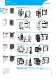
Descriptions: options and special versions
C: Option 3, 5, 54
LED (AC)
C: Option 6, 7, 74
Double LED
(DC non-polarized)
C: Option 8, 9, 94
LED + diode (DC, polarity
positive to pin 7) -
(56.32 only)
1
2
3
Lockable test button and mechanical flag indicator (0040, 0050, 0054, 0070, 0074, 0090,
0094)
The dual-purpose Finder test button can be used in two ways:
Case 1) The plastic pip (located directly above the test button) remains intact. In this case,
when the test button is pushed, the contacts operate. When the test button is released the
contacts return to their former state.
Case 2) The plastic pip is broken-off (using an appropriate cutting tool). In this case, (in
addition to the above function), when the test button is pushed and rotated, the contacts are
latched in the operating state, and remain so until the test button is rotated back to its former
position.
In both cases ensure that the test button actuation is swift and decisive.
E
U
R
O
P
E
A
N
E
U
R
O
P
E
A
N
PATENT