
Operation Manual


7
EN
following wiring instructions are followed.
The wires in the mains cable are coloured in
accordance with the following code:
blue neutral
brown live
As the colours of the wires in the mains cable of
the unit may not correspond to the coloured
markings identifying the terminals in the plug,
proceed as follows:
- The wire which is coloured blue must be
connected to the terminal which is marked with
the letter N or coloured black.
- The wire which is coloured brown must be
connected to the terminal which is marked with
the letter L or coloured red.
TECHNICAL DATA
AGM1029
Mains voltage V~ 230
Mains frequency Hz 50
Power input W 2,000
No-load speed min
-1
6,000
Grinding disc
Diameter mm 230
Bore mm 22
Spindle thread M14
Weight kg 5.7
NOISE AND VIBRATION
AGM1029
Sound pressure (L
pa
) dB(A) 94.5
Acoustic power (L
wa
) dB(A) 107.5
Uncertainty (K) dB(A) 3
Vibration m/s
2
6.63
Uncertainty (K) m/s
2
1.5
Vibration level
The vibration emission level stated in this
instruction manual has been measured in
accordance with a standardised test given in EN
60745; it may be used to compare one tool with
another and as a preliminary assessment of
exposure to vibration when using the tool for the
applications mentioned
- using the tool for different applications, or with
different or poorly maintainted accessories, may
signicantly increase the exposure level
- the times when the tool is switched off or when it
is running but not actually doing the job, may
signi cantly reduce the exposure level
Protect yourself against the effects of vibration by
maintaining the tool and its accessories, keeping
your hands warm, and organizing your work
patterns
2
Wear hearing protection.
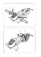
DESCRIPTION (FIG. A)
Your angle grinder has been designed for grinding
and cutting masonry and steel.
1. On/off switch
2. Lock-off button
3. Spindle lock button
4. Spindle
5. Guard
6. Main grip
7. Auxiliary grip
8. Release button for main grip
9. Carbon brush holder
ASSEMBLY
4
Before assembly, always switch off the
machine and remove the mains plug
from the mains.
2
Do not use the machine without the
guard.
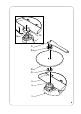
Mounting
● Place the machine on a table with the spindle
(4) facing upwards.
● Keep the spindle lock button (3) pressed and
remove the ange (10) using the ange key (11).
● If necessary, remove the grinding disc (12).
● Remove the ange (13).
● Mount the guard (5). Secure the guard (5) by
tightening the Allen screw (14) and the nut (15)
with the Allen key (16).
● Mount the ange (13).
● If necessary, mount the grinding disc (12).
● Keep the spindle lock button (3) pressed and
mount the ange (10) using the ange key (11).
Removing
● Place the machine on a table with the spindle
(4) facing upwards.
● Keep the spindle lock button (3) pressed and
remove the ange (10) using the ange key (11).
● If necessary, remove the grinding disc (12).