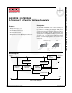
KA78XXE / KA78XXAE 3-Terminal 1 A Positive Voltage Regulator Description Features • • • • • The KA78XXE / KA78XXAE series of three-terminal positive regulators is available in the TO-220 / D-PAK package with several fixed-output voltages, making them useful in a wide range of applications. Each type employs internal current limiting, thermal shut-down, and safe operating area. If adequate heat sinking is provided, they can deliver over 1 A output current.
Product Number Output Voltage Tolerance KA7805ETU KA7806ETU KA7808ETU KA7809ETU KA7810ETU KA7812ETU KA7815ETU KA7818ETU KA7824ETU KA7805AETU KA7809AETU KA7810AETU KA7812AETU KA7815AETU KA7824AETU KA7805ERTF KA7805ERTM KA7808ERTM KA7809ERTM KA7812ERTM Package Operating Temperature Parking Method ±4% TO-220 (Dual Gauge) Rail 0°C to +125°C ±2% ±4% D-PAK Tape and Reel Note: 1. Above output voltage tolerance is available at 25°C. 2. Refer to below figure for TM / TF Suffix for DPAK.
Stresses exceeding the absolute maximum ratings may damage the device. The device may not function or be operable above the recommended operating conditions and stressing the parts to these levels is not recommended. In addition, extended exposure to stresses above the recommended operating conditions may affect device reliability. The absolute maximum ratings are stress ratings only.
Refer to test circuit, 0°C < TJ < 125°C, IO = 500 mA, VI =10 V, CI= 0.33 μF, CO=0.1 μF, unless otherwise specified. Symbol Parameter Conditions Min. Typ. Max. TJ = +25°C 4.80 5.00 5.20 Output Voltage 5.0 mA ≤ IO ≤ 1.0 A, PO ≤ 15 W, VI = 7 V to 20 V 4.75 5.00 5.25 Regline Line Regulation(3) TJ = +25°C VI = 7 V to 25 V 4.0 100.0 VI = 8 V to 12 V 1.6 50.0 Regload Load Regulation(3) TJ = +25°C IO = 5.0 mA to1.
Refer to test circuit, 0°C < TJ < 125°C, IO = 500 mA, VI = 11 V, CI = 0.33 μF, CO = 0.1 μF, unless otherwise specified. Symbol Parameter Conditions Min. Typ. Max. TJ = +25°C 5.75 6.00 6.25 Output Voltage 5.0 mA ≤ IO ≤ 1.0 A, PO ≤ 15 W, VI = 8.0 V to 21 V 5.70 6.00 6.30 Regline Line Regulation(5) TJ = +25°C VI = 8 V to 25 V 5.0 120.0 VI = 9 V to 13 V 1.5 60.0 Regload Load Regulation(5) TJ = +25°C IO = 5 mA to 1.
Refer to test circuit, 0°C < TJ < 125°C, IO = 500 mA, VI = 14 V, CI = 0.33 μF, CO = 0.1 μF, unless otherwise specified. Symbol Parameter Conditions Min. Typ. Max. Unit TJ = +25°C 7.7 8.0 8.3 Output Voltage 5.0 mA ≤ IO ≤ 1.0 A, PO ≤ 15 W, VI = 10.5 V to 23 V 7.6 8.0 8.4 Regline Line Regulation(7) TJ = +25°C VI = 10.5 V to 25 V 5 160 VI = 11.5 V to 17 V 2 80 Regload Load Regulation(7) TJ = +25°C IO = 5.0 mA to 1.
Refer to test circuit, 0°C < TJ < 125°C, IO = 500 mA, VI = 15 V, CI = 0.33 μF, CO = 0.1 μF, unless otherwise specified. Symbol Parameter Conditions Min. Typ. Max. TJ = +25°C 8.65 9.00 9.35 Output Voltage 5.0 mA ≤ IO ≤ 1.0 A, PO ≤ 15 W, VI = 11.5 V to 24 V 8.60 9.00 9.40 Regline Line Regulation(9) TJ = +25°C VI = 11.5 V to 25 V 6 180 VI = 12 V to 17 V 2 90 Regload Load Regulation(9) TJ = +25°C IO = 5 mA to 1.
Refer to test circuit, 0°C < TJ < 125°C, IO = 500 mA, VI = 16 V, CI = 0.33 μF, CO = 0.1 μF, unless otherwise specified. Symbol Parameter Conditions Min. Typ. Max. TJ = +25°C 9.6 10.0 10.4 Output Voltage 5.0 mA ≤ IO ≤ 1.0 A, PO ≤ 15 W, VI = 12.5 V to 25 V 9.5 10.0 10.5 Regline Line Regulation(11) TJ = +25°C VI = 12.5 V to 25 V 10 200 VI = 13 V to 25 V 3 100 Regload Load Regulation(11) TJ = +25°C IO = 5 mA to 1.
Refer to test circuit, 0°C < TJ < 125°C, IO = 500 mA, VI = 19 V, CI = 0.33 μF, CO= 0.1 μF, unless otherwise specified. Symbol Parameter Conditions Min. Typ. Max. TJ = +25°C 11.5 12.0 12.5 Output Voltage 5.0 mA ≤ IO ≤ 1.0 A, PO ≤ 15 W, VI = 14.5 V to 27 V 11.4 12.0 12.6 Regline Line Regulation(13) TJ = +25°C VI = 14.5 V to 30 V 10 240 VI = 16 V to 22 V 3 120 Regload Load Regulation(13) TJ = +25°C IO = 5 mA to 1.5 A 11 240 IO = 250 mA to 750 mA 5.
Refer to test circuit, 0°C < TJ < 125°C, IO = 500 mA, VI = 23 V, CI = 0.33 μF, CO = 0.1 μF, unless otherwise specified. Symbol Parameter Conditions Min. Typ. Max. TJ = +25°C 14.40 15.00 15.60 Output Voltage 5.0 mA ≤ IO ≤ 1.0 A, PO ≤ 15 W, VI = 17.5 V to 30 V 14.25 15.00 15.75 Regline Line Regulation(15) TJ = +25°C VI = 17.5 V to 30 V 11 300 VI = 20 V to 26 V 3 150 Regload Load Regulation(15) TJ = +25°C IO = 5 mA to 1.
Refer to test circuit, 0°C < TJ < 125°C, IO = 500 mA, VI = 27 V, CI = 0.33 μF, CO = 0.1 μF, unless otherwise specified. Symbol Parameter Conditions Min. Typ. Max. TJ =+25°C 17.3 18.0 18.7 Output Voltage 5.0 mA ≤ IO ≤ 1.0 A, PO ≤ 15 W, VI = 21 V to 33 V 17.1 18.0 18.9 Regline Line Regulation(17) TJ = +25°C VI = 21 V to 33 V 15 360 VI = 24 V to 30 V 5 180 Regload Load Regulation(17) TJ = +25°C IO = 5 mA to 1.
Refer to test circuit,0°C < TJ < 125°C, IO = 500 mA, VI = 33 V, CI = 0.33 μF, CO = 0.1 μF, unless otherwise specified. Symbol Parameter Conditions Min. Typ. Max. Unit TJ = +25°C 23.00 24.00 25.00 Output Voltage 5.0 mA ≤ IO ≤ 1.0 A, PO ≤ 15 W, VI = 27 V to 38 V 22.80 24.00 25.25 Regline Line Regulation(19) TJ = +25°C VI = 27 V to 38 V 17 480 VI = 30 V to 36 V 6 240 Regload Load Regulation(19) TJ = +25°C IO = 5 mA to 1.5 A 15 480 IO = 250 mA to 750 mA 5.
Refer to the test circuit, 0°C < TJ < +125°C, Io = 1 A, VI = 10 V, CI = 0.33 μF, CO = 0.1 μF, unless otherwise specified. Symbol VO Regline Parameter Output Voltage Line Regulation (21) Conditions Min. Typ. Max. TJ =+25°C 4.9 5.0 5.1 IO = 5 mA to 1 A, PO ≤ 15 W, VI = 7.5 V to 20 V 4.8 5.0 5.2 VI = 7.5 V to 25 V, IO = 500 mA 5.0 50.0 VI = 8 V to 12 V 3.0 50.0 VI= 7.3 V to 20 V 5.0 50.0 VI= 8 V to 12 V TJ = +25°C Regload IQ Load Regulation (21) Quiescent Current 1.5 25.
Refer to the test circuit, 0°C < TJ < +125 °C, IO = 1 A, VI = 15 V, CI = 0.33 μF, CO = 0.1 μF, unless otherwise specified. Symbol VO Parameter Output Voltage Conditions Min. Typ. Max. TJ = +25°C 8.82 9.00 9.18 IO = 5 mA to 1 A, PO ≤ 15 W, VI = 11.2 V to 24 V 8.65 9.00 9.35 6 90 VI = 11.7 V to 25 V, IO = 500 mA Regline Line Regulation (23) VI = 12.5 V to 19 V TJ = +25°C Regload IQ ΔIQ ΔV/ΔT Load Regulation(23) Quiescent Current Quiescent Current Change Drift(24) 4 45 VI = 11.
Refer to the test circuit, 0°C < TJ < +125 °C, IO = 1 A, VI = 16 V, CI = 0.33 μF, CO = 0.1 μF, unless otherwise specified. Symbol VO Parameter Output Voltage Conditions Min. Typ. Max. TJ =+25°C 9.8 10.0 10.2 IO = 5 mA to 1 A, PO ≤ 15 W, VI = 12.8 V to 25 V 9.6 10.0 10.4 8.0 100.0 VI = 12.8 V to 26 V, IO = 500 mA Regline Line Regulation (25) VI = 13 V to 20 V TJ = +25°C Regload IQ ΔIQ ΔV/ΔT Load Regulation(25) Quiescent Current 4.0 50.0 VI = 12.5 V to 25 V 8.0 100.
Refer to the test circuit, 0°C < TJ < +125°C, IO = 1 A, VI = 19 V, CI= 0.33 μF, CO = 0.1 μF, unless otherwise specified. Symbol VO Parameter Output Voltage Conditions Min. Typ. Max. TJ = +25°C 11.75 12.00 12.25 IO = 5 mA to 1 A, PO ≤ 15 W, VI = 14.8 V to 27 V 11.50 12.00 12.50 10 120 VI = 14.8 V to 30 V, IO = 500 mA Regline Line Regulation(27) VI= 16 V to 22 V 4 120 VI= 14.5 V to 27 V 10 120 VI= 16 V to 22 V 3 60 TJ = +25°C, IO = 5 mA to 1.5 A 12 100 IO = 5 mA to 1.
Refer to the test circuit, 0°C < TJ < +125°C, IO = 1 A, VI = 23 V, CI = 0.33 μF, CO = 0.1 μF, unless otherwise specified. Symbol VO Parameter Output Voltage Conditions Min. Typ. Max. TJ = +25°C 14.7 15.0 15.3 IO = 5 mA to 1 A, PO ≤ 15 W, VI = 17.7 V to 30 V 14.4 15.0 15.6 10 150 VI = 17.9 V to 30 V, IO = 500 mA Regline Line Regulation (29) VI = 20 V to 26 V TJ = +25°C Regload IQ ΔIQ ΔV/ΔT Load Regulation(29) Quiescent Current 5 150 VI = 17.
Refer to the test circuit, 0°C < TJ < +125°C, IO =1 A, VI = 33 V, CI = 0.33 μF, CO = 0.1 μF, unless otherwise specified. Symbol VO Parameter Output Voltage Conditions Min. Typ. Max. TJ = +25°C 23.5 24.0 24.5 IO = 5 mA to 1 A, PO ≤15 W, VI = 27.3 V to 38 V 23.0 24.0 25.0 18 240 VI = 27 V to 38 V, IO = 500 mA Regline Line Regulation (31) VI = 21 V to 33 V 6 240 VI = 26.7 V to 38 V 18 240 VI = 30 V to 36 V 6 120 TJ = +25°C, IO = 5 mA to 1.5 A 15 100 IO = 5 mA to 1.
Figure 2. Quiescent Current Figure 3. Peak Output Current Figure 4. Output Voltage Figure 5. Quiescent Current © 2006 Fairchild Semiconductor Corporation KA78XXE / KA78XXAE Rev. 1.1.1 www.fairchildsemi.
1 KA78XXE 3 Output Input CO 2 CI 0.33 μF 0.1 μF Figure 6. DC Parameters 1 KA78XXE 3 Input Output 270 pF RL 2 VO 2N6121 OR EQ 0.33 μF OV 30 μS VO 100 Ω Figure 7. Load Regulation 5.1 Ω 1 KA78XXE Input 3 Output 0.33 μF 2 RL 470 μF 120 Hz + Figure 8. Ripple Rejection © 2006 Fairchild Semiconductor Corporation KA78XXE / KA78XXAE Rev. 1.1.1 www.fairchildsemi.
KA78XXE 3 Output Input CO 2 CI 0.33μF 0.1μF Figure 9. Fixed Output Regulator 1 3 KA78XXE Output Input CI CO 2 0.33 μF 0.1 μF Vxx R1 IQ IO RL Vxx IO = + R1 IQ Figure 10. Constant Current Regulator Notes: 33. To specify an output voltage, substitute voltage value for “XX”. A common ground is required between the input and the output voltage. The input voltage must remain typically 2.0 V above the output voltage even during the low point on the input ripple voltage. 34.
1 Output 3 KA7805E 2 CI 0.33μF 6 CO - 2 KA741 + 3 4 0.1μF 10KΩ IRI ≥ 5 IQ VO = VXX(1+R2/R1) + IQR2 Figure 12. Adjustable Output Regulator (7 V to 30 V) Input VI IQ1 R1 1 3Ω Output 3 KA78XXE Vo Io IREG 2 0.33 μF 0.1 μF IO = IREG + BQ1 (IREG-VBEQ1/R1) Figure 13. High-Current Voltage Regulator Q1 Input VI Q2 R1 1 3Ω KA78XXE 3 Vo Output 0.33 μF Q1 = TIP42 Q2 = TIP42 RSC = 2 0.1 μF VBEQ2 ISC Figure 14.
KA78XXE / KA78XXAE — 3-Terminal 1 A Positive Voltage Regulator 1 3 KA78XXE VO VI 2 0.33 μF 0.1 μF 7 COMMON 6 _ COMMON 2 KA741 + 4 -VIN 4.7 kΩ 3 4.7 kΩ -VO TIP42 Figure 15. Tracking Voltage Regulator 1 KA7815E 3 +20 V +15 V 2 0.1 μF 0.33 μ F + 2.2 μF 1 μF + 1N4001 1 -20 V 2 1N4001 KA7915E 3 -15 V Figure 16. Split-Power Supply (±15 V - 1 A) © 2006 Fairchild Semiconductor Corporation KA78XXE / KA78XXAE Rev. 1.1.1 www.fairchildsemi.
Input + 0.1 μF 2 1 KA78XXE Figure 17. Negative Output Voltage Circuit D45H11 Input 1mH Output 470 Ω 4.7 Ω Z1 1 + KA78XXE 0.33 μF 10 μF 0.5 Ω 3 2 + 2000 μF Figure 18. Switching Regulator © 2006 Fairchild Semiconductor Corporation KA78XXE / KA78XXAE Rev. 1.1.1 www.fairchildsemi.
KA78XXE / KA78XXAE — 3-Terminal 1 A Positive Voltage Regulator Physical Dimensions TO-220 (DUAL GAUGE) Figure 19. TO-220, MOLDED, 3-LEAD, NON-JEDEC, VARIATION AB (DUAL GUAGE) Package drawings are provided as a service to customers considering Fairchild components. Drawings may change in any manner without notice. Please note the revision and/or date on the drawing and contact a Fairchild Semiconductor representative to verify or obtain the most recent revision.
KA78XXE / KA78XXAE — 3-Terminal 1 A Positive Voltage Regulator Physical Dimensions D-PAK Figure 20. 3-LEAD, TO-252, JEDEC TO-252 VAR. AB, SURFACE MOUNT (DPAK) Package drawings are provided as a service to customers considering Fairchild components. Drawings may change in any manner without notice. Please note the revision and/or date on the drawing and contact a Fairchild Semiconductor representative to verify or obtain the most recent revision.
TRADEMARKS The following includes registered and unregistered trademarks and service marks, owned by Fairchild Semiconductor and/or its global subsidiaries, and is not intended to be an exhaustive list of all such trademarks.