
- Extron Electronics User's Manual Hub/Switch MVX 44, MVX 48, MVX 84, MVX 88


Remote Operation, cont’d
MVX 44 / 48 / 84 / 88 VGA Matrix Switchers • Remote Operation4-2
Remote Operation
The MVX VGA Series switchers can be remotely controlled via the switcher’s rear
panel RS-232 connector (figure 4-1) or using an optional infrared Small Matrix
Universal Remote Control (figure 4-2).
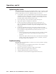
Pin RS-232 Function
1 — Not used
2 TX Transmit data (-)
3 RX Receive data (+)
4 — Not used
5 Gnd Signal ground
6 — Not used
Not used
Not used
7—
8—
—
51
96
Female
Hardwired IR9
Figure 4-1 — Remote connector pinout
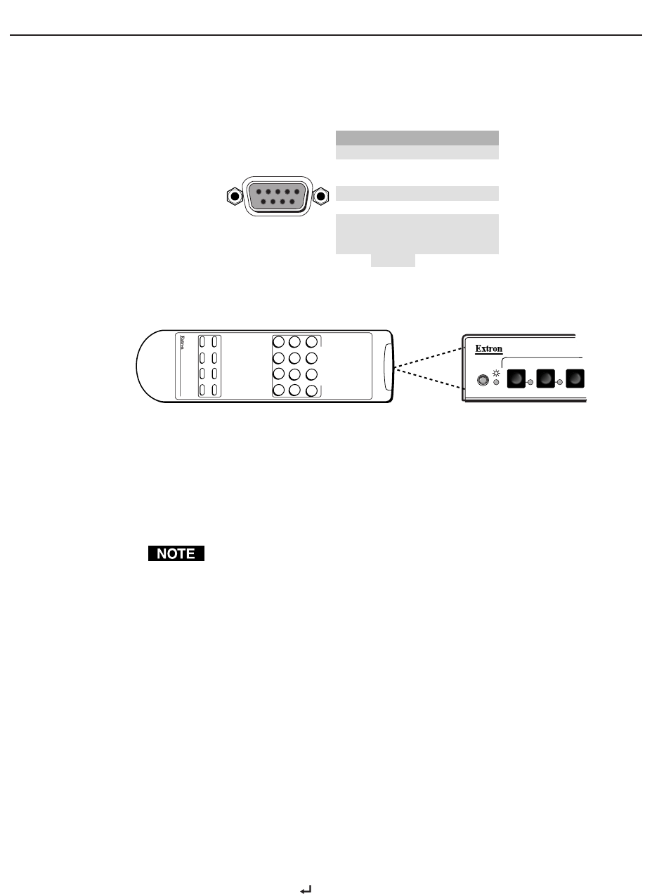
SMALL MATRIX REMOTE
INPUT/OUTPUT SELECTION
1234
5678
PRESET SAVE VIDEO AUDIO
MUTE UNMUTE INPUT OUTPUT
9 0 +10 ENTER
IR 501
IR
2
1
3
Extron
IR 501 Remote, Part # 70-336-01
Figure 4-2 — Small matrix IR remote control
The RS-232 protocol is 9600 baud, 8-bit, 1 stop bit, no parity, and no flow control.
RS-232 remote control devices can be either a host device, such as a computer or a
control system.
When using communications software such as HyperTerminal to control the
MVX switcher, verify that the terminal emulation is set to Auto Detect or
ANSI and set flow control to None. Other settings may cause errors.
Two remote control methods are available: Extron’s Simple Instruction Set and
Extron’s Windows-based Matrix Switchers Control Program.
Operation of the IR 501 remote control is described in the IR 501 Small Matrix IR
Remote Control User’s Guide.
Using the hardwired IR input on pin 9, you can use a control system with
IR-learning capabilities to operate the switcher just as if you were using an IR 501
remote control. The control system must first “learn” the IR command from an
IR 501, after which, it sends the same commands to the MVX via pin 9.
Simple Instruction Set Control
Host-to-Switcher instructions
The switcher accepts SIS (Simple Instruction Set) commands through the
RS-232 port. SIS commands consist of one or more characters per command field.
They do not require any special characters to begin or end the command character
sequence. Each switcher response to an SIS command ends with a carriage return
and a line feed (CR/LF = ), which signals the end of the response character
string. A string is one or more characters.