
User's Manual


Installation, cont’d
Matrix 50 Series Switchers • Installation2-2
Installation
Rack Mounting the Switcher
The Matrix 50 Series Switchers are housed in rack-mountable, 2U high, 19” wide
metal enclosures. The appropriate rack mount kit is included with each switcher.
Rack mount the switcher as follows:
1. Insert the switcher into the rack, align the holes in the mounting bracket with
those of the rack.
2. Secure the switcher to the rack using the supplied machine screws.
Cabling and Rear Panel Views
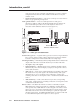
All connectors are on the rear panel. Figure 2-1 shows a 12x8 Matrix 50 component
video and audio switcher. Figure 2-2 shows a 12x8 Matrix 50 S-video switcher
without an audio module. Figure 2-3 shows a 12x8 Matrix 50 composite video and
audio switcher. Figure 2-4 shows a 12x8 Matrix 50 audio switcher. The 8x4, 8x8,
and 12x4 matrixes are housed in the same 2U enclosure, but have fewer input and/
or output connectors to accommodate the different matrix sizes each provides.
12 34 5 6 78 9101112
12345678
1
6
7
4 5
3
2
Figure 2-1 — Rear panel connectors, Matrix 50 component video and
audio switcher
1
6
7
3
2
Figure 2-2 — Rear panel connectors, Matrix 50 S-video switcher
12 34 5 6 78 9101112
12345678
1
6
7
4 5
3
2
Figure 2-3 — Rear panel connectors, Matrix 50 composite video and
audio switcher
12 34 5 6 78 9101112
12345678
1
6
7
4 5
Figure 2-4 — Rear panel connectors, Matrix 50 audio switcher