M X - 8 0 TYPE II EPSON DOT MATRIX PRINTER Operation Manual EPSON P8190014-2
TABLE OF CONTENTS ........................................ 1 1. Introduction . . . . . . . . . . . . . . . . . . . . . . . . . . . . . . . . . . . . . . . . . . . . . . . . . . 2. Characteristics . . . . . . . . . . . . . . . . . . . . . . . . . . . . . . . . . . . . . . . . . . . . . . . . 1 2 3 GENERAL DESCRIPTION INSTALLATION OF MX-80 TYPE II . . . . . . . . . . . . . . . . . . . . . . . . . . . . . . . 1. Unpacking . . . . . . . . . . . . . . . . . . . . . . . . . . . . . . . . . . . . . . . . . .
OPERATION . . . . . . . . . . . 1. Switches and Indicators 1.1. Switches . . . . . . . . . . 1.2. Indicators . . . . . . . . . ................................. . . ................................. . . ................................. . . ................................. . . . . . . 36 . . . . . 36 . . . . . 36 . . . . . 37 . . . 38 1.3. Printer initial check . . . . . . . . . . . . . . . . . . . . . . . . . . . . . . . . . . . . . . . 2. Buzzer . . . . . . . . . . . . . . . . . . . . . . . . . . . .
LIST OF FIGURES Fig. 1 EPSON MX-80 Type II Fig. 2 Contents of Carton . . . Fig. 3 Laying Printer on Firm Fig. 4 Assembly Tools . . . . . and MX-80 F/T Type II Dot Matrix Printers ... ...................................... Surface . . . . . . . . . . . . . . . . . . . . . . . . . . . . . . . 1 4 ...................................... 5 6 Fig. 5 Removal of Shipping Screws . . . . . . . . . . . . . . . . . . . . . . . . . . . . . . . . . Fig. 6 Removal of Printer Lid . . . . . . . . . . . . . . . . . . .
Fig. 41 Alignment of Side Edges . . . . . . . . . . . . . . . . . . . . . . . . . . . . . 32 Fig. 42 Form Position Setting Mark . . . . . . . . . . . . . . . . . . . . . . . . . . . 32 Fig. 43 Print Area . . . . . . . . . . . . . . . . . . . . . . . . . . . . . . . . . . . . . . . . . 3 2 Fig. 44 Setting of Cut Paper Sheet . . . . . . . . . . . . . . . . . . . . . . . . . . . . 33 Fig. 45 Printer with Cut Paper Sheet Set Completely . . . . . . . . . . . . . . 33 Fig. 46 Gap Adjustment . . . . . . . . . . .
LIST OF TABLES T a b l e 1 I n t e r f a c e S i g n a l s i n P a p e r - O u t S t a t u s. . . . . . . . . . . . . . . . . 39 Table 2 Functions and Conditions of DIP Switch No. 1 . . . . . . . . . . . . . . . . . . . . . . . . . . . . . . . . 4 5 Table 3 Character Size and Maximum Column Length . . . . . . . . . . . . . . . . . 4 6 Table 4 Functions and Conditions of DIP Switch No. 2 . . . . . . . . . . . . . . . 46 T a b l e 5 I n t e r n a t i o n a l C h a r a c t e r S e t D e s i g n a t i o n . . .
GENERAL DESCRIPTION 1. Introduction Ideal for computer business applications, the MX-80 Type II Dot Matrix Printer is the latest extension of EPSON advanced printer technology. This new printer couples innovative design and precision manufacturing with long life, low cost, light weight and superior performance. The MX-80 Type II features a 9 x 9 dot matrix print head that can be replaced easily, and 80 CPS bidirectional printing with logic seeking capability.
2. Characteristics The MX-80 Type II and MX-80 F/T Type II have been designed as a printer with versatile functions to meet a wide range of applications from small business to home uses and even for hobbies. The following is a brief summary of their major characteristics. (1) Both text printing for general data processing and Bit Image printing for graphic data processing are freely available.
INSTALLATION OF MX-80 TYPE II 1. Unpacking Before removing the MX-80 Type I I from the carton, check the box for evidence of shipping damage or mishandling. If such evidence is present, notify the carrier immediately. 1.1. Unpacking steps Unpacking steps are as follows: STEP 1. Open the carton. STEP 2. Remove accessories. STEP 3. Remove the MX-80 Type I I holding its underside and lifting it straight up with the packing material attached. STEP4.
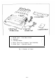
1. MX-80 Type I I Dot Matrix Printer 2. Separator 3. Cartridge Ribbon 4. Power Cord (Only European Type 220/240V) 5. MX-80 Type I I Operation Manual Fig.
3. Installation of the Printer (1) Operating site selection When installing the MX-80 Type I I, observe the following instructions. (a) Place the Printer on a bench, tabletop or any other convenient flat surface with enough room for the separator in the back of the Printer. Your layout may look like Fig. 3. NOTE: Rubber feet are provided to prevent the marring of the surface on which the MX-80 Type I I is placed.
(2) Removal of protective paper for paper end detector The MX-80 Type II is provided with a protective paper inserted between the inner and outer paper guides to protect the paper end detector from damage due to shocks or vibrations during transportation. Before using the Printer, be sure to remove this paper. If the MX-80 Type II is to be reshipped, remember to return it to the original position. (3) Prepare tools Prepare the following two tools to disassemble or assemble the printer. 1 pc.
Right Side of the Printer Fig. 5 Removal of Shipping Screws NOTE: Save the two shipping screws for possible future use. < SUPPLEMENT > l If the printer lid is an obstacle when removing the shipping screws, be sure to take off the printer lid by observing the following steps. Rough or careless handling of the printer lid may result in damage to, or even breakage of, its hinges. STEP 1. Stand the printer lid upright. STEP 2. Push the printer lid toward the right and pull up its left side. (See Fig. 6.
When remounting the printer lid, be sure to observe the following steps: STEP 1. Fit the right side of the printer lid onto the projection located at the right corner of the Printer’s upper case. (See Fig. 7.) STEP 2. Fit the left side of the printer lid onto the left projection and push the printer lid down, Fig. 7 Remounting of Printer Lid 4. Cartridge Ribbon Setting EPSON’s Cartridge Ribbon is compact, long-lasting, and very easy to set and remove.
STEP 4. Put the ribbon between the head nose and the ribbon mask. In this case, the ribbon can be set easily by hooking it to the edge of the head nose and turning the ribbon feeding knob of the cartridge case in the direction of the arrow (i.e., counterclockwise) while depressing the ribbon with a ball-point pen. Then, tension the ribbon by turning the ribbon feeding knob counterclockwise. (See Fig. 9.) I NOTES: Fig. 9 Cartridge Ribbon Setting 1. Incorrect setting of the ribbon may cause it to come off.
5. Separator Installation The separator of the Printer contributes to smooth paper feeding. Set the separator by inserting its edge into the two holes located at the rear part of the frame of the printer mechanism. (See Fig. 11.) Fig. 11 Separator Installation 6. Paper Loading 6.1. Loading of fanfold paper The MX-80 Type II Printer accommodates fanfold paper from 4” to 10” in width. To load the fanfold paper, observe the following procedure. STEP 1. Raise the printer lid. STEP 2.
Fig. 12 Insertion of Fanfold Paper STEP 5. Push the paper into the insertion slot between the paper guides at the rear part of the printer mechanism. NOTE: Be sure to pass the paper beneath the upper paper guide. STEP 6. After the leading edge of the paper has emerged from the Printer, pull it out gently to some length.
STEP 7. Raise the two sprocket lock levers to loosen, and adjust the sprocket pin position to the paper width. (See Fig. 13.) Fig. 13 Raising of Sprocket Lock Levers STEP 8. Engage the paper feed holes of the paper on the feeding pins, push the scale back into position, and adjust the tension of the paper. Then push the paper holding covers and the two sprocket lock levers down. (See Fig. 14.) NOTE: In this case, confirm that the feeding pins are centered in the respective paper feed holes of the paper.
STEP 9. Put the printer lid on the Printer. Fig. 15 Printer with Fanfold Paper Set Completely NOTE: When the MX-80 Type II is to be used on a desk or a bench, arrangement of the fanfold paper in parallel with the MX-80 Type II as shown below will permit the paper to be folded in an accordion style. Fig. 16 Example of Paper Arrangement 6.2. Removal of fanfold paper To remove the fanfold paper, follow either of the two methods described below.
6.3. Column layout on fanfold paper When fanfold paper of from 4” to 10” in width is supplied with the MX-80 Type I I, the graduations on the scale can be used as the indexes of print column positions (1 to 80). Alignment of the print start position on fanfold paper with the 1st column position at the extreme left of the scale will facilitate column layout. Accordingly, center the paper by adjusting it to these indexes of the scale. 6.4.
7. Gap Adjustment The adjustment of a gap between the head nose and the platen is used to adjust the printing pressure as well as to suit paper of a different thickness. (1) Move the head adjusting lever (located on the left frame of the Printer) forward or backward to adjust the gap between the head nose and the platen. (See Fig. 18.) Forward: To widen gap. Backward: To narrow gap. NOTE: With a thick paper, be sure to widen this gap.
-16-
INSTALLATION OF MX-80 F/T TYPE II 1. Unpacking Before removing the MX-80 F/T Type II from the carton, check the box for evidence of shipping damage or mishandling. If such evidence is present, notify the carrier immediately. 1.1. Unpacking steps Unpacking steps are as follows: STEP 1. Open the carton. STEP 2. Remove accessories. STEP 3. Remove the MX-80 F/T Type I I by holding its underside and lifting it straight up with the packing material attached. STEP 4.
1. MX-80 F/T Type II Dot Matrix Printer 2. Separator 3. Cartridge Ribbon 1 4. Power Cord (Only European Type 220/24OV) 1 5. MX-80 F/T Type I I Operation Manual 1 1 1 Fig. 19 Contents of Carton 3. Installation of the Printer (1) Operating site selection When installing the MX-80 F/T Type I I, observe the following instructions. (a) Place the Printer on a bench, tabletop or any other convenient flat surface with enough room for the separator in the back of the Printer. Your layout may look like Fig.
(e) Avoid use of the Printer in humid locations or in the vicinity of heat generating sources such as heater, etc. Fig. 20 Laying Printer on Firm Surface (2) Removal of protective paper for paper end detector The MX-80 F/T Type II is provided with a protective paper inserted between the inner and outer paper guides to protect the paper end detector from damage due to shocks or vibrations during transportation. Before using the Printer, be sure to remove this paper.
(4) Removal of shipping screws The purpose of the shipping screws is to protect the MX-80 F/T Type I I against any damage that may be caused by shocks or vibrations during transportation. Therefore, before operating the MX-80 F/T Type II, remove the screws as described below. (See Fig. 22.1 Stand the printer on its left side. STEP 1. STEP 2. Remove with a screwdriver, the two shipping screws visible on the underside of the lower case.
STEP 1. STEP 2. Stand the printer lid upright. Push the printer lid toward the right and pull up its left side. (See Figs 23 (1) and (2).) NOTE: The printer lid shown in Fig. 23 (2) is an Optional accessory.
4. Cartridge Ribbon Setting EPSON’s Cartridge Ribbon is compact, long-lasting, and very easy to set and remove. Furthermore, you have no need to soil your fingers in handling it. STEP 1. Open the printer lid (or remove it). STEP 2. Confirm that the scale (paper retainer) is turned toward the platen and STEP 3. is touching. Push the cartridge ribbon down and set it on the printer mechanism.
NOTES: 1. Incorrect setting of the ribbon may cause it to come off. (See Fig. 26.) 2. Confirm that the ribbon is neither twisted nor creased and that the cartridge is set properly. Fig. 26 Examples of Correct and Incorrect Ribbon Setting 5. Separator Installation The separator of the Printer contributes to smooth paper feeding. Set the separator by inserting its edge into the two holes located at the rear part of the frame of the printer mechanism. (See Fig. 27.) I Fig.
6. Dismounting of Tractor Unit The tractor unit of the MX-80 F/T Type I I is detachable. If it is an obstacle when using roll paper, it can be taken out as follows; STEP 1. Release the lock levers of the tractor unit by pulling in the direction as shown in Fig. 28. STEP 2. Keep pulling the levers and pull up the tractor unit. Fig. 28 Dismounting of Tractor Unit To install the tractor unit, hook the notches of the tractor frames onto the shaft shown in Fig. 29 and then push down the tractor unit. Fig.
7. Paper Loading 7.1. Fanfold paper 7.1.1. Loading of fanfold paper The MX-80 F/T Type I I Printer accommodates fanfold paper from 4” to 10” in width. To load the fanfold paper, observe the following procedure. STEP 1. Raise the printer lid. STEP 2. Unlock the release lever by pulling it in the direction of the arrow. (See Fig. 30.) STEP 3. Pull the scale toward the front of the Printer to detach the scale from STEP 4. the platen.
STEP 8. STEP 6. Raise the two sprocket lock levers to loosen, and adjust the sprocket pin position to the paper width. (See Fig. 31.) Engage the paper feed holes of the paper on the feeding pins, push the scale back into position, and adjust the tension of the paper. Then push the paper holding covers and the two sprocket lock levers down. (See Fig. 32.) NOTE: In this case, confirm that the feeding pins are centered in the respective paper feed holes of the paper. Do not lock the release lever.
STEP 10. Put the printer lid on the Printer. (See Fig. 33.) NOTE: When the MX-80 F/T Type I I is to be used on a desk or a bench, arrangement of the fanfold paper in parallel with the MX-80 F/T Type II as shown below will permit the paper to be folded in an accordion style. 7.1.2. Removal of fanfold paper To remove the fanfold paper, follow either of the two methods described below. (1) To disengage the paper from the paper holding mechanism, pull it forward out of the Printer.
7.1.3. Column layout on fanfold paper When fanfold paper of from 4” to 10” in width is supplied with the MX-80 F/T Type II, the graduations on the scale can be used as the indexes of print column positions (1 to 80). Alignment of the print start position on fanfold paper with the 1st column position at the extreme left of the scale will facilitate column layout. Accordingly, center the paper by adjusting it to these indexes of the scale. 7.1.4.
7.2. Roll paper 7.2.1. Roll paper holder EPSON offers the roll paper holder as an optional accessory for the MX-80 F/T Type II. See Appendix 7 for the assembly instructions on Roll Paper Holder. 7.2.2. Loading of roll paper The MX-80 F/T Type II accommodates a roll of single ply paper measuring 8.5 ±0.12 in. in width with a 1 in. core. To load it, observe the following procedure. STEP 1. Raise the printer lid. STEP 2. Unlock the release lever by pulling it in the direction of the arrow. (See Fig. 36.
7.3. Cut paper sheet 7.3.1. Loading of cut paper sheet The MX-80 F/T Type I I accommodates cut paper sheets measuring 8.3” to 8.5” in width. To load a cut paper sheet, observe the following procedure. STEP 1. Raise the printer lid. STEP 2. STEP 3. Unlock the release lever. (See Fig. 39.) Pull the scale toward the front of the Printer to detach the scale from the platen. (See Fig. 39.) STEP 4. Confirm that the paper guide roller is at the center of the sprocket shaft.
STEP 6. Lock the release lever. STEP 7. While turning the manual paper feed knob clockwise, confirm that the paper advances straight up. (See Fig. 40.) Fig. 40 Adjustment of Inserted Paper Position If not, adjust the inserted paper position as follows: a) If the cut paper sheet or form is long enough, unlock the release lever and align the side edges of the paper as shown in Fig. 41.
b) If the cut paper sheet or form is not long enough to align the side edges, align the top edge of the paper with the form position setting mark on the tractor unit. (See Fig. 42.) Fig. 42 Form Position Setting Mark The print area on the cut paper sheet (when printing it with the tractor unit installed) is shown in Fig. 43 Fig.
Fig. 44 Setting of Cut Paper Sheet NOTES: 1. The Paper End Detector function may be disabled under software control (ESC 8; refer to page 66) provided printing is left off within 7.5 mm from the paper bottom edge. 2. If the paper is set on the line marked l/4 as shown in Fig. 44, then the printing starts from a position 28.6 mm below the top edge of the paper. If the paper is set on the line marked l/8, then the printing starts from a position 30.2 mm below the top edge of the paper. STEP 8.
8. Gap Adjustment The adjustment of a gap between the head nose and the platen is used to adjust the printing pressure as well as to suit paper of a different thickness. (1) Move the head adjusting lever (located on the left frame of the Printer) forward or backward to adjust the gap between the head nose and the platen. (See Fig. 46.) Forward: To widen gap. Backward: To narrow gap. NOTE: With a thick paper, be sure to widen this gap.
-35-
OPERATION 1. Switches and Indicators There are three switches and four indicators (green LED’s) on the control panel and one power switch on the right side of the Printer case. In this section, panel operating procedures are covered in sufficient detail for the user to become familiar with the Printer. (See Fig. 47 for the control panel.) 1.1. Switches POWER SW: Controls primary AC power to the Printer. NOTE: Before turning this switch on, check to see if the paper is properly set in the Printer.
FF SW: (Form Feed) When this switch is depressed once, the paper is advanced vertically to the next Top of Form position. This switch must be depressed while the Printer is OFF-LINE. Otherwise, the form feed operation will not be carried out. The Top of Form position is initialized when the POWER switch is turned on or when INIT signal is applied to the interface connector. Therefore, before turning the POWER switch on to start operating the Printer, set the paper at the appropriate Top of Form position.
1.3. Printer initial check Take the following steps and become familiar with the Printer.
2. Buzzer The buzzer is located inside the Printer case, and sounds for about one second when the Printer receives BE L code (H). (See page 66 for the BE L code.) 3. Paper End Detector (1) When the paper end detector (a reed switch located on the paper guide) detects that the paper is nearly exhausted, the signals on the interface connector change to the following status, and the printing operation stops. Table 1 Interface Signals in Paper-Out Status Signal Pin No.
(2) When the Printer falls into paper-out status, it is automatically put in the OFF-LINE state and paper advancement can be performed by depressing the LF switch. After setting new paper in the Printer, depress the ON LINE switch so that the Printer may resume operation. (3) There is another way to start the Printer again when it falls into paper-out status. Set new paper in the Printer, and turn the POWER switch off and on again, or apply the INIT signal.
5. Setting of DIP Switches In order to suit the user’s specific requirements, desired control modes are selectable by the two built-in DIP switches. The DIP switches (SW1 and SW2) located on the control circuit board of the Printer are as shown in Fig. 54. To gain access to the DIP switches, the upper case of the Printer must be removed. NOTE: Turn the power off whenever you attempt to open up the printer case.
Tip the printer right side up again. Gently loosen the upper case. Lift up the cover from the left side. And then pull out the wires hooked to the control panel on the right. (See Fig. 52.) Fig.
See the inside of the printer before you set the switches. The printer consists of a printer mechanism, a controller, a transformer and filter circuit board, and a control panel. (See Fig. 53.
Position the printer as shown in Fig. 53. There are two “DIP” (DUAL IN-LINE PACKAGE) switches in the HMTP board. (See Fig. 54.) The switches set to the left are ON . . . to the right are OFF. (See Fig. 55.) Each switch No. of the DIP switch functions as described below. So set these switches to suit your application or the computer’s specifications. NOTE: Be sure that the POWER switch of the printer is turned off before changing switch positions.
5.1. Setting of DIP Switch No. 1 The DIP switch No. 1 consists of the following 8 pins. A summary of the functions of the respective DIP switch pins and their preset conditions at the time of shipment are shown in Table 2. Table 2 Functions and Conditions of DIP Switch No. 1 (1) SW1-1: Setting this pin to the ON position will cause the line spacing to be automatically set at 1/8 inch per line upon power application.
(8) Character sizes and maximum column lengths can be specified as follows; Table 3 Character Size and Maximum Column Length Character size Pin number SW1-3 Default length Maximum column length SW1-4 Normal OFF OFF 80 80 Condensed OFF ON 132 132 Emphasized ON ON 80 80 If you turn any of the above character sizes to the enlarged character print mode, then the maximum column length will be reduced to a half of them. 5.2. Setting of DIP switch No. 2 The DIP switch No.
5.3. Coding tables Appendix 3 shows all available codes when the Printer is set for operation with standard coding by setting the DIP switch pins l-7, 2-l and 2-2 all to ON position. Table 5 shows International Character Set Designation according to the combination of the DIP switch setting. Table 5 International Character Set Designation The above settings can be changed to any country character sets by inputting ESC R + n control codes. (Described later.
5.4. Setting sequence of functional specifications The MX-80 Type I I has a choice of various functional specifications such as amount of line spacing, form length per page, number of columns per line, automatic skip-over perforation, etc. for selection under the control of both hardware (DIP switches) and software (control codes) which is described later. In Figs. 56 through 59, setting sequence of these functional specifications are illustrated. Fig.
Fig.
Fig.
Fig.
WHAT IS THE MX-80 TYPE II? This chapter describes the MX-80 Type II from the viewpoint of hardware and software. The contents of the chapter are; 1, What is a dot matrix printer? 2. Definitions of some terms often used. 3. Control codes in the text mode 4. Control codes in the bit image mode This printer has two different print modes. One is the text mode, and another is the bit image mode. You might be familiar with the text mode because an ordinary printer has it.
The dot matrix printing method allows a printer to easily form any desired character. It has a print head that contains 9 needles vertically and can create distinctive characters like with typewriter. In that sense it is one of the key features that the printer has. EPSON’s MX-80 Type II can control each needle programmably, expanding the ability of the printer. See next how the print head works and forms a character. (1) Dot Matrix Printer The print head contains 9 “needles” or “wires” vertically.
(2) Character and line spacing Line spacing means the pitch from the top of dots that form a character on a line to the top of dots on the next line. It is absolutely necessary to separate characters vertically for ease in reading each sentence. Most typewriters and printers have a switch or lever to change the line spacing (1/6” or 1/8”). The MX-80 Type II also can do this by DIP switch setting, of course. In addition, you can set it programmably with some ESC codes with a range from 1/72” to 85/72”.
If you are already familiar with the above terms, skip these paragraphs. (1) ASCII code Characters in computer systems are represented by groups of bits. The various groups of bits that represent the set of characters that are the “alphabet” of any given system are called a “coding system,” or simply “code.” Codes for representing the information vary in relation to both the number of bits used to define a single character in the assignment of bit patterns to each particular character.
(3) “+” symbol You will see “+" symbol often in the explanation or description of control codes from now on. This symbol is used for legibility only and may not be input in your actual program. (4) 2, D (or Dec.) and H (or Hex.) ( )2 , ( )D a n d < >H r e s p e c t i v e l y r e p r e s e n t b i n a r y , d e c i m a l a n d h e x a decimal numbers. 3. Control Codes in the Text Mode With the MX-80 Type II, two standard operation modes are available.
(4) Other codes DC1, DC3.. Selection or deselection of the printer ESC8. ESC9. . . Selection or deselection of the paper end detector BEL . . . . . . . . Bell Back space BS . . . . . . . . NUL . . . . . . . ESC K, ESC L . Null Access code to Bit Image mode (described later). 3.1. Print action codes (1) CR (Carriage Return) When the CR code is transmitted to the print buffer, all data stored in the print buffer is printed. When AUTO FEED XT (Pin No.
NOTES: 1. The Top of Form is determined when the POWER switch is turned on or the INIT signal is applied. 2. If the form length per page is not set, one page length of form is regarded as 66 lines with the DIP switch pin 1-2 on the control circuit board set in the OFF position or 72 lines with the DIP switch pin 1-2 set in the ON position. (The amount of line spacing is governed by the DIP switch setting at that time.
(3) ESC Q + n The print column width can be specified by inputting ESC Q + n code. “n” represents the print column width to be specified in character size at the time of input.
(4) ESC A + n (for setting amount of line spacing) This code specifies the amount of line spacing in the Line Feed, provided that ( n ) D must satisfy the condition: (Decimal). “ n ” = 1 is equivalent to 1/72 inch paper advancement. Since the distance between any two dot wires of the print head is 1/72 inch, any line spacing in increments proportional to the distance between the dot wires can be established. NOTES: 1. When the POWER switch is turned on or INIT signal is applied to the pin No.
(5) ESC 0 Input of the ESC 0 causes the subsequent line spacing to be set at 1/8 inch. (6) ESC 2 Input of the ESC 2 causes the subsequent line spacing to be set at either 1/6 inch or 1/8 inch depending on the initial set condition of the DIP switch pin 1-1. (7) VT (Vertical Tabulation) See paragraph 3.1 (3) above. ( 8 ) E S C B + n1 + nz + . . . +nk + N U L This code specifies the vertical tab stop positions.
(9) FF (Form Feed) See paragraph 3.1 (4) above. (10) ESC C + n (n # 0), ESC C + [0] H + m (for setting form length) The “ESC C t n” code specifies the form length which is determined by the number of lines where the value of “n” is a positive number and must not exceed 127 lines). In other words, the maximum form length is 127 lines. The amount of line spacing when this code is input is a predetermined numerical value by ESC A + n.
(12) ESC 0 This code cancels the skip-over perforation set by the ESC N + n code. 3.3. Character designation codes (1) SO (Shift Out) (for enlarged characters) When the SO code is input, all data that follows it in the same line will be printed out in enlarged (double width) characters. This code is cancelled by the printing operation or the input of “DC 4” code and can be input at any column position on a line. Therefore, normal size and enlarged characters can be mixed on the same line.
(2) SI (Shift In) (for condensed characters) When the SI code is input, all data that follows it will be printed out in condensed characters. This code is cancelled by the input of “DC 2” code. The SI code can be input at any column position on a line, but all characters/ symbols on the line containing SI code are printed out in condensed characters. Normal and condensed characters cannot be mixed on the same line.
(7) ESC E (for emphasized characters) The ESC E code causes the Printer to print emphasized characters. Emphasized printing gives the character a stronger impression on the paper. This code can be input in any column position on a line, but all characters on the line containing ESC E code are printed out in emphasized characters. The speed of the head carriage reduces to 40 CPS while printing emphasized characters. (8) ESC F The ESC F code cancels the emphasized printing mode.
3.4. Other codes (1) DC 1 (Device Control 1) The DC 1 code places the Printer in the Selected state. It enables the Printer to receive data. With the Printer in the Selected state, if the DC 1 code is input during data transfer, all data stored before the DC 1 code is ignored. (2) DC 3 (Device Control 3) The DC 3 code places the Printer in the Deselected state. In other words, it disables the Printer to receive data.
(7) NUL (Null) The NUL code is regarded as the termination for tabulation setting sequence. The lack of the NUL code would cause incorrect data printout. (8) ESC K Input of this code in the Text Mode causes the Printer’s operation mode to be converted from Text to Normal-density Bit Image. Refer to paragraph 4.1, section 4, for details. (9) ESC L Input of this code in the Text Mode causes the Printer to perform dual-density bit image printing. Refer to paragraph 4.2, section 4, for details. 4.
4.1. Normal-density bit image mode setting by ESC K + nl + n2 To convert the printer’s operation mode from Text to Normal-density Bit Image, t h e “ E S C K + nI + n2 ” code must be input. (Here, the sign “+" is inserted for the purpose of legibility only and should not be input in actual operation.) Namely, w h e n E S C ( < 1 B >H ) a n d K ( < 4 B > H ) codes and data n l a n d n2 a r e i n p u t , t h e Printer recognizes the data following the “ESC K” as the bit image data.
(Ex. 4) Bit image data transfer by standard BASIC program To check for proper conversion to the Normaldensity Bit Image mode, execute the following program.
4.2. Dual-density bit image mode setting by ESC L + n1 + n2 W h e n t h e E S C ( < 1 B >H) and L (<4C> H) codes followed by data n l a n d n2 a r e input, the printer’s operation mode is converted from Text to Dual-density Bit Image. The transfer sequence of bit image data is the same as with the ESC K (normaldensity bit image printing), but bit image printing can be performed in twice the dot density in the horizontal direction as with the ESC K.
4.3. Relationship between data and dot wires Fig. 68 shows the relationship between the Bit Image data and the dot wires in the print head. You can control arbitrary 8 dot wires in the print head. If a bit is “1," the print head fires. If a bit is “0,” the print head does not fire. For example, assume that data are given as follows; where a box with “•” denotes the bit “1” and a blank b o x denotes the bit “0.
4.4 How to obtain n1 and n2 In the Type II Printer, you have send the number of data by n 1 + n2 in hexadecimal numbers following the ESK K or ESC L. If the number of bit image data is 300, then n1 and n2 may be derived as follows; n1 = (Number of data) MOD 256 = 300 MOD 256 = (44)D = < 2 C >H n2 = INT (Number of data/256) = INT (300/256) = (1) D = < 0 1 >H You can also use Appendix 3, Code Table, to find the corresponding hexadecimal numbers to the decimal numbers.
4.5. Programming examples (1) Dual-density bit image printing Fig. 65 Example of Graphic Pattern Formation NOTE: The most significant bit (MSB) of the bit image data corresponds to the dot wire at the uppermost position. For example, to print a graphic data as shown in Fig. 65, a program such as shown below must be executed. However, this program has been developed using standard BASIC language. If extended BASIC is to be used, the program must be changed according to the features of the language.
(2) Normal-density bit image printing -74-
(3) Difference between ESC K and ESC L The normal-density mode is accessed with ESC K. The dual-density mode is accessed with ESC L. Fig. 66 Normal-Density and Dual-Density Modes NOTE: Print alignment under the friction feed. EPSON is carefully applying printer mechanisms of better quality for MX-80 Type II and MX-80 F/T Type II.
(4) Example of CRT screen dump hard copy This print example is made using APPLE II computer and the demonstration diskette. Fig.
(5) Example of expression of brightness using the Bit Image Mode Fig.
MAINTENANCE 1. Preventive Maintenance Preventive maintenance for the MX-80 Type II and MX-80 F/T Type I I (hereafter referred to as “Type II Printer”) consists basically of cleaning. The Printer should be cleaned with a soft brush to remove paper dust and particles after every three months of use. The exterior surface of the Printer can be cleaned by using a mild detergent and water solution. 2.
*Take hold of the cable at the point indicated by arrows and apply force in either of the directions Indicated by arrow to push in or pull out the head cable. Fig.
SPECIFICATIONS (1) PRINT METHOD: (2) PRINT SPEED: Serial impact dot matrix 80 CPS (3) PRINT DIRECTION: Bidirectional with logical seeking Unidirectional in the bit image mode (4) NUMBER OF PINS IN HEAD: (5) LINE SPACING: 9 4.23 mm (1/6”) or 3.
SPECIFICATIONS (continued) 5 x 10⁶ lines (excluding print head) (11) MCBF: (12) ENVIRONMENTAL CONDITIONS Operating Temperature Range: 5 to 35°C (41 to 95°F) Operating Humidity: 10 to 80% non-condensing (13) POWER REQUIREMENT Voltage: 115v, 60Hz 220/24OV, 50Hz Current: 1 Amp maximum 100 VA maximum Power Consumption: (14) PHYSICAL CHARACTERISTICS MX-80 TYPE II 107 mm (4.2”) MX-80 F/T TYPE II Height: Width : 374 mm (14.7”) 374 mm (14.7”) Depth: W eight: 305 mm (12.0”) 5.5 kg (12 Ibs.) 305 mm (12.
APPENDIX 1 Construction of MX-80 Type II and MX-80 F/T Type II The EPSON MX-80 Type I I and MX-80 F/T Type II dot matrix printers (hereinafter referred to as “Type II Printer”) consist of the following three major functional blocks. (1) Printer Mechanism (2) Control Circuit Board (3) Power Circuit These three blocks are housed in a plastic case and are connected to one another. 1.1. Printer mechanism The printer mechanism has been developed by EPSON Shinshu Seiki C O ., Ltd.
Fig.
1.3. Power circuit The power circuit generates 5V DC for the logic circuit, and 24V DC to energize the solenoids of the print head and two stepper motors. 1.4. Printer initialization Printer initialization is accomplished in either of the two ways described below. (1) Initialization takes place automatically each time the primary AC power source is interrupted and reapplied (i.e., by turning the Power Switch off and on).
APPENDIX 2 Parallel Interface Both the MX-80 Type II and MX-80 F/T Type II include a parallel interface as the standard equipment, and this paragraph describes the parallel interface. (1) Specifications (a) Data transfer rate: (b) Synchronization: (c) Handshaking: (d) Logic level: 1000 CPS (min.) By externally supplied STROBE pulses. By ACKN LG or BUSY signals. Input data and all interface control signals are compatible with the TTL level.
Table A2-1 (cont’d) Description This signal indicates that the printer is in the selected state. With this signal being at “LOW” level, the paper is automatically fed one line after printing. (The signal level can be fixed to “LOW’ with DIP SW pin 2-3 provided on the control circuit board.) Not used. Logic GND level. Printer chassis GND. In the printer, the chassis GND and the logic GND are isolated from each other. Not used. TWISTED-PAIR RETURN signal GND level.
(4) Data transfer sequence Fig. A2-1 shows the sequence for data transmission. Relations among the ON LINE switch, SLCT IN signal, DC 1/DC 3 code and interface signals are shown in Table A2-2 below.
NOTES: 1. In Table A2-2, it is assumed that as soon as the Printer receives data, it sends back the ACKNLG signal, though this data is not stored in the print buffer. In this status, the Printer is waiting for the DC 1 code for normal entry. 2. In the above table, it is also assumed that no ERROR status exists other than that attributable to the OFF-LINE position of the ON LINE switch. In the ERROR status, the Printer is not in the Selected state (SLCT = “LOW”). 3.
APPENDIX 4 Character Fonts -92-
NOTE: Numbers represent Hex.
-94-
-95-
APPENDIX 5 Control Codes
FEDERAL COMMUNICATIONS COMMISSION RADIO FREQUENCY INTERFERENCE STATEMENT “This equipment generates and uses radio frequency energy and if not installed and used properly, that is, in strict accordance with the manufacturer’s instructions, may cause interference to radio and television reception.
EPSON SHINSHU SElKl CO., LTD. EPSON OVERSEAS MARKETING LOCATIONS EPSON AMERICA, INC. (L.A.) EPSON AMERICA, INC. (N.Y.) 3415 Kashiwa St. Torrance, Calif., 90505 Phone: (213) 539-9140 Telex: (230) 182412 98 Cutter Mill Road Great Neck, New York, 11021 Phone: (516) 487-0660 Telex: (25) 510223-0743 EPSON DEUTSCHLAND GMBH EPSON U.K. LTD. Am Seestern 24 4000 . DÜsseldorf 11 F.R. Germany Phone: (0211) 596-1001 Telex: (41) 8584786 Sherwood House 176 Northolt Road South Harrow HA2 OEB U.K.