
Product Information Guide


Table Of Contents
ExpressStation
Main System Board Jumpers
The computer contains four blocks (groups) of jumpers: J3, JS,
119,
and J21. To access jumper blocks
119
and J21, you must
remove any option cards that are installed. You must remove the
drive housing to access jumper blocks J3 and
JS.
Caution
Do not install or
remow
any option cards when the
driw
housing is
removed from the computer. The housing stabilizes the option card riser
board and you could severely damage it if you put stress on it without
the support of the drive housing. Also, do not change the settings in the
reserved jumper block
JlO;
these jumpers must remain at their factory
settings.
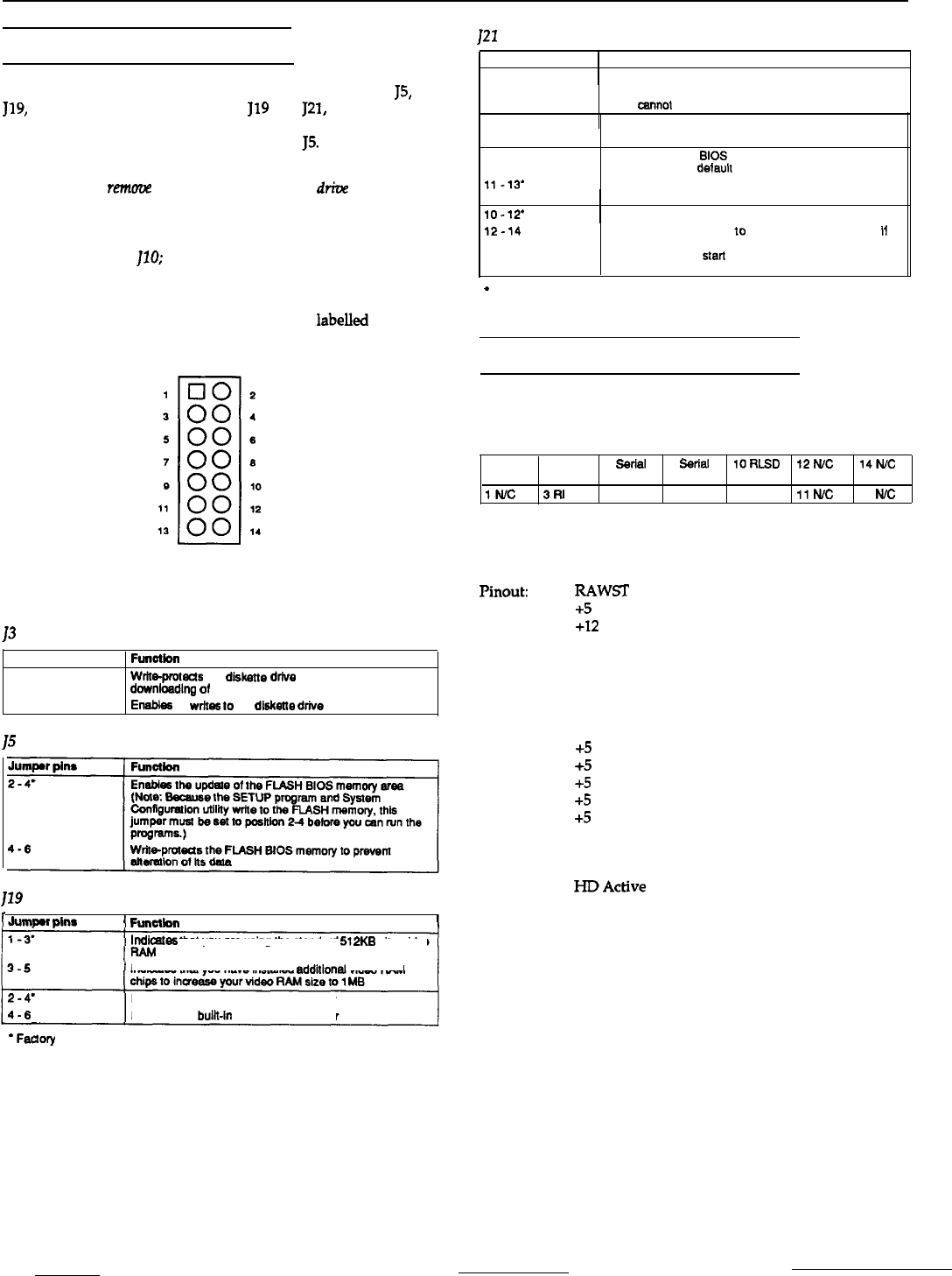
Each jumper block consists of 14 jumper pins, as shown below.
Certain pin numbers and jumper functions are
labelled
beside
each jumper block on the main system board.
The tables below list the jumper settings available in each jumper
block.
13
Settings
Jumper pins
2-4
4-6’
15
Settings
Function
Wrb-protecis
the dlhkstte drtve to prevent unauthorized
dow’nloadlng
of software onto a diskette
Enebks
all
writes
10
the diskette drive
119
Settings
I
Jummr oins
1
Funcilon
I
Indkntes
that you are using the standard 512KB size video
Indicates that you have installed
additlonal
video RAM
*
Faclory setting
Enables the bulk-in VGA display adapter
Disables the
bulk-in
VGA display adapter
121
Settings
Jumper pins
1
Function
i-3’
1
Enables you to use the BIOS SETUP program
3-5
2-4
Disables use of the BIOS SETUP program so unauthorized
users
canno
change the
settings you have chosen
Clears the power-on password
4-6
9-11
11-13’
10-12’
Retains the power-on password
Clears the current
BIOS SETUP information in CMOS
memory and sets delault parameters
Retains the current BIOS SETUP information in CMOS
memory
1
Sets normal FLASH memory operation
12-14
Sets the FLASH memory
10
operate in recovery mode
I1
you unsuccessfully attempted lo download updated BIOS
information; allows
start
of a procedure lo restore the
previous BIOS information
*
Factory setting
Main System Board Connectors
J1-Internal Serial Port 1 Header
Type: 3M style header, double row (Male)
2 GND
4 DTR
6 Serial 6
ssrlal 10RLSD
I2N.C
14fvc
Data Out
Data In
IN/C
3Rl
5CTS
7
RTS
9 DSR
11
tvc
13
N/c
J2-Power Connector
Type: Single Row Header Style (Male)
Pinout:
1
RAWST
2
+5
3
+12
4
-12
5
GND
6
GND
7
GND
8
GND
9
-5
10
+5
11
+5
12
+5
13
+5
14
+5
15
GND
16
GND
17
-12
18
HDActive
19
Front Panel Reset
20
Speaker Data
J4-Dual Serial Port Connector
Type: Stacked Dual 9-Pin D-sub (Male)
Pinout: PC AT standard
J6A-Parallel Port
Type: 25-pin Centronics type (Female)
Pinout: PC AT standard
ExpressStation Computer
5/12/92
ExpressStation-3