
User Manual


5
Temperature setting: 5°C to 35°C in 0.5°C increments
Temperature dierential: 0.2°C
Operating temperature: 0°C to 40°C
Storage temperature: -20°C to 60°C
Unit interconnection: via 868 MHz radio signal
Transmitter unit range: up to 100 m in an open area
Power supply:
Control unit (transmitter): 2× 1.5 V AAA batteries
Switching unit (receiver): 230 V AC/50 Hz
Dimensions and weight:
Control unit: 28 × 120 × 77 mm; 117 g
Switching unit: 26 × 86 × 86 mm; 146 g
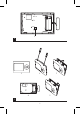
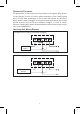
Display Description (See Fig. 1)
1 – Operating mode
2 – Cooling mode
3 – Low battery indication
4 – Set temperature
5 – Room temperature
6 – Heating mode
Control Button Description
Thermostat (Transmitter Unit) (See Fig. 2)
1 – Control/conrmation button
Receiver (Switching Unit) (See Fig. 3)
2 – Main switch
position – o
position – on
3 – M/A button (red LED)
4 – MANUAL button (green LED)
Rear of the Thermostat (See Fig. 4)
5 – LEARN button for pairing units
Procedure for Removing the Front of the Thermostat (See Fig. 5)
2, 3 – Use a screwdriver to press down and hold the inner lock, remove
the front cover
Procedure for Removing the Front of the Switching Unit (See Fig. 6)
2, 3 – Use a screwdriver to press down and hold the inner lock, remove
the front cover
INSTALLATION
Warning:
Before changing the thermostat, disconnect the heating/air-conditioning
system from the main power in your at. This will prevent potential injury
by electric current.
Thermostat Installation
The rear of the thermostat carries 4 openings for mounting onto a wall.
Use the enclosed screws and wall plugs to mount the thermostat.