BP7354 CF200 9/19/07 11:30 AM Page 1 READ AND SAVE THESE INSTRUCTIONS CITYSCAPE™ Ceiling Fan Owner's Manual Model Numbers CF200NI00 CF200GES00 Brushed Nickel with Black/Brushed Nickel Blades Golden Espresso with Black/Teak Blades Net Weight: Part No. F40BP73540001 22.1 Lbs. Form No. BP7354-1 U.L. Model No.
BP7354 CF200 9/19/07 11:30 AM Page 2 ! WARNING WARNING: To avoid fire, shock, and serious personal injury, follow these instructions. Safety Instructions 1. Read your owner’s manual carefully and keep it for future reference. 2. Before servicing or cleaning unit, switch power off at service panel and lock service panel disconnecting means to prevent power from being switched on accidentally.
BP7354 CF200 9/19/07 11:30 AM Page 3 This Manual Is Designed to Make it as Easy as Possible for You to Assemble, Install, Operate and Maintain Your Ceiling Fan 1. Open styrofoam unit containing fan. Remove top half of styrofoam unit. Remove parts and check to see that you have received the following parts: NOTE: If you are uncertain of part description, refer to exploded view illustration.
BP7354 CF200 9/19/07 11:30 AM Page 4 Preset Memory Feature 2. Remove the fan motor and housing assembly from the protective plastic bag. Place the fan assembly into the lower foam pad with the bottom of the motor facing up. The lower foam pad serves as a holder for the fan during the first stages of assembly. Your remote control receiver is equipped with a preset memory feature. The receiver will remember the light intensity and fan speed when the light and fan are turned off from the wall switch.
BP7354 CF200 9/19/07 11:30 AM Page 5 2. Slide the four switch levers on the code switch to your choice of ON (up) or down positions. Use a ball-point pen or small screwdriver and slide the levers firmly up or down. 3. In the receiver (Figure 1), slide the four switch levers to the same positions as set in the transmitter. Make sure the levers on both switches are in the same positions, otherwise the fan will not operate. 4.
BP7354 CF200 9/19/07 11:30 AM Page 6 4. Position the blade flange on the motor hub so that the screws in the blade flange align with the two threaded holes in the motor hub. Tighten the two screws securely. Repeat this procedure for the remaining two blade assemblies. 1/4-20 x 11mm PAN HEAD SCREW WITH LOCKWASHER (2) be mated correctly (color-to-color) before they can be engaged. Make sure the connectors close properly. 7.
BP7354 CF200 9/19/07 11:30 AM Page 7 9. Carefully remove the fan assembly from the lower foam pad. Turn the fan assembly over and position it on the lower foam pad with the fan blades resting on the pad so that the top of the motor faces up. ! WARNING It is critical that the clevis pin in the motor coupling is properly installed and the setscrews securely tightened. Failure to verify that the pin and setscrews are properly installed (as shown in Figure 8) could result in the fan falling. 10.
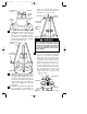
BP7354 CF200 9/19/07 ROD SUPPORT ASSEMBLY 11:30 AM Page 8 GROMMET (SCREWS TOWARD TOP) MOTOR HOUSING (Figure 11). Hold the rod support in this position while tightening all six decorative rod screws securely. ROD SUPPORT ASSEMBLY DOWNROD COUPLING COVER Figure 9 15. Using the decorative rod screws (supplied), attach the three decorative rod assemblies to the motor housing (Figure 10). The decorative rods must be oriented so that they lean in towards the downrod.
BP7354 CF200 9/19/07 11:30 AM Page 9 19. The fan comes with blue, black and white leads that are 80” long. Before installing the fan, measure up approximately 6 to 9-inches above top of hanger ball/downrod assembly. Cut off excess leads and strip back insulation 1/2” from end of leads. 1. Securely attach the hanger bracket to the outlet box using the two screws supplied with the outlet box (Figure 14). ! 20. You have now completed the initial assembly of your new ceiling fan.
BP7354 CF200 9/19/07 11:30 AM Page 10 How to Wire Your Ceiling Fan If you feel that you do not have enough electrical wiring knowledge or experience, have your fan installed by a licensed electrician. ! WARNING Turning off wall switch is not sufficient. To avoid possible electrical shock, be sure electricity is turned off at the main fuse box before wiring.
BP7354 CF200 9/19/07 TO 120VOLT SUPPLY 11:30 AM Page 11 STANDARD ON-OFF WALL SWITCH OR OPTIONAL SW101 WALL CONTROL BLACK BLACK (HOT) BLACK WHITE WHITE WHITE GROUND RED TWO-CONDUCTOR CABLE (WITH GROUND) BLUE WHITE BLACK BLUE WHITE GREEN WIRE (GROUND) FROM HANGER BALL AND HANGER BRACKET Figure 17 HANGER BALL 3. Push the wires and connectors up into the outlet box while inserting the receiver fully into the hanger bracket. Position the antenna wire on top of the receiver. 4.
BP7354 CF200 9/19/07 11:30 AM Page 12 8. Place the lower glass into the light fitter, aligning the three flat areas on the top flange of the lower glass with the three pins on the inside of the fitter (Figure 19). Then turn the lower glass clockwise until it stops turning. MED HI 9. Your ceiling fan is now installed and wired to be controlled by your remote control system.
BP7354 CF200 9/19/07 11:30 AM Page 13 Maintenance Accessories IMPORTANT CARE INSTRUCTIONS for your Ceiling Fan 1. Downrod Extension Kits (see store or catalog). Periodic cleaning of your new ceiling fan is the only maintenance that is needed. 2. Ceiling Fan Controls (see store or catalog). When cleaning, use only a soft brush or lint free cloth to avoid scratching the finish. ! The use of any other control not specifically approved for this fan could result in fire, shock and personal injury.
BP7354 CF200 9/19/07 11:30 AM Page 14 WARNING: FOR YOUR OWN SAFETY TURN OFF POWER AT FUSE BOX ! OR CIRCUIT BREAKER BEFORE TROUBLE SHOOTING YOUR FAN. Trouble Shooting TROUBLE 1. Fan will not start. PROBABLE CAUSE 1. Fuse or circuit breaker blown. 2. Loose power line connections to the fan, or loose wire connections in the switch housing. 3. Wall switch is off. 4. Defective battery in remote control transmitter. 5.
BP7354 CF200 9/19/07 11:30 AM Page 15 Repair Parts Listing Key No. * 1 2 3 * 4 5 6 7 8 9 10 11 12 13 14 15 16 17 18 19 20 21 22 23 24 25 26 27 28 29 30 — Part Numbers Model No. Model No.
BP7354 CF200 9/19/07 11:30 AM Page 16 LIMITED WARRANTY What The Warranty Covers: This warranty covers the motor and the other components and accessories of your Emerson ceiling fan against all defects in workmanship and materials. You must be the original purchaser or user of the product to be covered. What The Period Of Coverage Is: As it applies to the motor, this warranty will last for the lifetime of your ceiling fan.