
User's Manual


Low Frequency Exciters - Installation Guide _________________________________________________________________________________________
Page 3 of 8
DTA03N01_V13
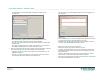
To wire a Master/Slave configuration, use an unshielded 4 conductor 26 AWG solid
cable crimped at both ends with a RJ45 (8P8C) connector as illustrated below:
When the Master LF Exciter (from hardware Version C, Revision A-1) senses that the Slave
has been disconnected, the B1 bit on the RF supervision transmission is set to Down.
Flush Mounting to Drop Ceilings or Interior Hollow Walls
1. Separate the LF Exciter from its base by pressing one of the snaps (identified by a
square hole) using a small screwdriver.
2. Then cut a 5 inch (12.7 cm) diameter mounting hole in the drop ceiling or the hollow
wall where the LF Exciter is to be flush mounted.
3. Pull the 6P6C power cable (for master
slave configurations the additional 8P8C
interface cable as well) trough the cable
entry hole of the RDR1 mounting bracket
and the LF exciter base.
4. Insert the RDR1 mounting bracket
through the mounting hole and position
it carefully so it is firmly supported.
5. Insert the base of the exciter into the mounting hole. Next, screw the base to the RDR1
mounting bracket place using the 2 supplied screws. Ensure that the screw heads are
recessed inside the screw holes. If not the LF Exciter will not close properly and damage
may occur.
6. Connect the power and interface cables to the LF Exciter; set the DIP switch and adjust
the units' output power. Then, insert the LF Exciter back into its base.
7. Finally walk test the LF Exciter using either an Elpas LF Meter or an active Elpas
Tag/Badge to verify that the placement and output power of the device is correct.
Surfacing Mounting to Solid Ceilings or Walls
1. Separate the LF Exciter from its base by pressing one of the snaps (identified by a
square hole) using a small screwdriver.
2. Using the base of the exciter as a template mark the locations of the two mounting
holes and the cable pass through.
3. Drill holes at the marked areas to accommodate the required mounting hardware and
the diameter of the power and interface cables.