Service Manual
Easy Travel – Service Manual Rev.
Table of contents: 1. System components and details 4 2. Annual maintenance service 5 3. Spare parts replacement 6 4. Programming 46 5. Fault finding 48 6. Electrical wiring 49 7. Charger 50 8. Spare parts 51 9. List of Tool Types 54 NOTE: Design details may change without notice Easy Travel – Service Manual Rev.
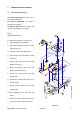
1. SYSTEM COMPONENTS AND DETAILS 1.1 EasyTravel parts – (Figure 1) 1. Battery pack (detachable) 2. Front column (detachable) 3. Column lock/release triggers 4. Controller cover 5. Charging socket (Fig. 1A) 6. Front drive wheels 7. Foot platform 8. Seat shell 9. Seat cushions 10. Serial # up to and including: folding seat latch 11. Rear wheel 12. Folded frame lock pin 13. Platform bottom lock pin 14. Utility basket (holding capacity 9kg) 15. Charger and connecting cables (Fig. 1B). 16. Control Panel 17.
2. SERVICE For reasons of safety and the prevention of accidents caused by wear which is not detected in time, the EasyTravel should be tested and serviced once a year. All safety-related components of the EasyTravel should be checked and serviced, safety and functional tests should be performed. It is important to detect initial wear in time and to use exclusively original spares, or such parts that were authorized by the manufacturer.
3. SPARE PARTS REPLACEMENT 3.1 Control Panel Assembly Kit number E0-00-1-040 (for serial # up to and including 0307076) Kit Number E0-00-1-202 (for serial # 0307077 and onwards) Kit Number E0-00-1-701 (for serial # with 13 digits, starting with 11B (Taiwan)) Tools: Phillips #2 Screwdriver For serial # and onwards, see next page. 1. Push Handgrips (4-A) outwards 2. Open Screws (4-B) and remove Control Panel Cover (4-C) 3. Disconnect the Control Cable (4-D) 4.
Kit Number E0-00-1-202 Kit Number E0-00-1-701 Tools: Phillips #2 Screwdriver 1. Open Screws (5-A) and remove top and bottom Control Panel Cover (5-B, C) 2. Disconnect the Control Cable (5-D) 3. Open Screws (5-E) and remove Control Panel (5-F) 4. Secure new Control Panel (5-F) with Screws (5-E) 5. Connect the Control Cable (5-D) to Control Panel (5-F) 6. Secure top and bottom Control Panel Cover (5-B, C) with Screws (5-A) 7.
3.2 Handgrip pair Kit number E0-00-1-070 Tools: Silicone spray Phillips #2 Screwdriver 1. Remove Control Panel Assembly, see instructions 3.1 2. For serial # up to and including 0307076: open Screws (6-A) and remove Control Panel Bottom Cover (6B) Figure 6 3. Remove the Handgrips, (7-A) 4. Spray Handlebars (7-B) of the Column Frame and inside of the new Handgrips lightly with Silicone Spray and push them onto the Column Frame 5. Reassemble Control Panel Bottom Cover and Control Panel Assembly 6.
3.3 Controller Cover ET1B Kit Number E0-00-1-034 Kit Number E0-00-1-705 (for serial # starting with 11B) Tools: Phillips #2 Screwdriver 1. Remove Screws (8-A) at the top and bottom of the Controller Cover (8-B) and remove Cover 2. Disconnect Connector (8-C) from Interface Circuit Board (8-D) 3. Check that the solder tabs of the Freewheel Switch on new Cover are bent apart 4. Insert Connector of new Cover (8-C) to Interface Circuit Board 5.
3.4 Solo Controller ET1B Kit Number E0-00-1-032 Kit Number E0-00-1-704 (for serial # starting with 11B) Tools: Short Phillips #2 Screwdriver Pliers 1. Remove Controller Cover, see instruction 3.3 2. Detach wiring from Controller (9-A) 3. Remove Controller (9-A) by unscrewing Screws (9-B) 4. Secure new Controller to Column Frame 5. Attach Wires to Controller (Fig.
Kit Number E0-00-1-704 (for serial # starting with 11B) Tools: Short Phillips #2 Screwdriver Pliers 1. Remove Controller Cover, see 3.3 2. Open Screws (10-A), remove Controller Top and plastic protection sheet 3. Detach wiring from Controller 4. Open Screws (10-B) on reverse side of Steering Column and remove Controller 5. Secure new Controller to Column Frame 6. Attach Wires to Controller (Fig. 10a): Figure 10 a. Control Cable (C); b. from Contacts and Charging Socket Assembly: i.
3.5 Battery Contacts Kit number E0-00-1-059 Tools: Phillips #2 Screwdriver 1. Remove Controller Cover, see instruction 3.3 2. Disconnect wiring to Controller (11-A) and Interface Circuit Board (11-B) 3. Unscrew Screws (11-C) and remove Battery Contacts Assembly (11-D) 4. Secure new Battery Contacts Assembly (11-D) with Screws (11-C) 5. Connect Wiring (11-A) to Controller (red to “B+” tab, black to “B-“ tab), Connector (11-B) onto Interface Circuit Board 6.
3.6 Interface Circuit Board ET1B Kit number E0-00-1-058 Tools: Phillips #1 Screwdriver Phillips #2 Screwdriver 1. Remove Controller Cover, see instruction 3.3 2. Disconnect Control Cable (12-A), Freewheel Cable (12-B), wiring to Controller (12-C), Contact Pins Assembly (12-D) and to Power Cable (12-E) 3. Unscrew 3 Screws (12-F) and remove Interface Circuit Board (12-G) 4. Secure new Interface Circuit Board (12G) with Screws (12-F) Figure 12 5. Connect Control Cable (Fig.
3.7 Contacts and Charging Socket Assembly Kit number E0-00-1-703 (for serial # starting with 11B) Tools: Phillips #1 Screwdriver Phillips #2 Screwdriver 1. Remove Controller Cover, see instruction 3.3 2. Open Controller, see instruction 3.4 3. Disconnect wiring to Controller and to Power Cable, see instruction 3.4 4. Unscrew 3 Screws (12a-A) and two Screws (12a-B) 5. Remove Contacts and Charging Socket Figure 12a Assembly (12a-C) and replace 6. Secure new Assembly (12a-C) with Screws (12a-A, B) 7.
3.8 Control Cable Kit number E0-00-1-054 Kit Number E0-00-1-702 (for serial # starting with 11B) Tools: Phillips #2 Screwdriver 1. Open Control Panel Cover, see instruction 3.1 2. Open Controller Cover, see instruction 3.3 3. Disconnect Control Cable from Control Panel (5-C) and Interface Circuit Board (12-A)/Controller (10a-C) 4. Remove Control Cable 5. Insert new Control Cable (if needed, remove the Paint Protector and replace it with a new one after the Control Cable is inserted, see instruction 3.
3.9 Motor End Cover ET1B Kit Number E0-00-1-083 (for motor types E0-00-1-036 and E0-00-1-092) Tools: Phillips #2 Screwdriver 1. Unscrew Screw (13-A) and remove Cover (13-B) 2. Note the motor wire routing and maintain it in position NOTE: If force is needed to fit Cover, check the wire routing and ensure that it will not be pinched 3. Secure new Cover (13-B) with Screw Figure 13 (13-A) Kit Number E0-00-1-096 (for motor type E0-00-1-094) Tools: Phillips #2 Screwdriver 1.
3.10 Motor Brushes Kit Number E0-00-1-037 (for serial # up to and including 0304599) Tools: Phillips #2 Screwdriver Flat Blade Screwdriver (For EasyTravel with serial number up to and including 0212052: Hot Air Gun (if available) Soldering Iron and Solder) Please refer to Figure 13 1. Remove the Motor End Cover, see instruction 3.8 2. Remove the plastic Brush Cap (C) and pull the Brush gently from its housing 3.
3.
7. Thread the new Power Cable from the Controller-end into the hole in the Column Frame out of tube and under the Adapter Block, as depicted in Fig. 16 8. Connect the #1/red insulated Wire end to positive/red colored Terminal, the #2/black insulated Wire end to negative/black Terminal, the #3 and green Wire to white Wires from electromagnetic Brake (For serial # up to and including 0212052: a.
3.12 Front Wheel Assembly Kit Number E0-00-1-069 Tools: Allen Key 6 mm Loctite Adhesive #242 (1312) Soft Mallet 1. Remove old Cap (18-A), Screw (18-B), Disk (18-C) and Wheel (18-D) 2. Thoroughly clean the threaded hole in the end of the Axle (18-E) of adhesive residue 3. Slide the Wheel (18-D) onto Axle (18-E) aligning the groove in the Adapter with the Roll Pin on the Axle 4. Place Disk (18-C) on Screw (18-B) and apply Loctite #242 (1312) adhesive to the screw thread Figure 18 5.
3.13 Gear Motor Kit Number E0-00-1-035 (ET1) Kit Number E0-00-1-094 (ET1B) Tools: Phillips #2 Screwdriver Allen Key 5 mm Cable Tie Tensioning Tool Loctite Adhesive #242 (1312) (For serial # up to and including 0212052: Soldering Iron Solder) 1. Remove Front Wheels, see instruction 3.11 2. Remove the Motor End Cover, see instruction 3.8 (for serial # starting with 11B it is not needed to remove Motor End Cover) 3. Detach Power Cable from Gear Motor, see instruction 3.10 4.
3.14 Adapter Block Assembly Kit Number E0-00-1-038 Kit Number E0-00-1-707 (for serial # starting with 11B) Tools: Allen key 5 mm Allen Key 8 mm Wrench, open end 19 mm Torque Wrench Loctite Adhesive #242 (1312) Light Grease/Lubricant The wheels MAY be removed to facilitate easier access, see instruction 3.11 1. Open Screw (20-A) and remove Clip (20-B) 2. Unscrew the four Screws (20-D) securing Gear Motor (20-E) to the Adapter Block (20-F) and put Gear Motor aside 3.
9. Remove Screw (22-A) holding Pin (22B) 10. Remove the Pin from the new Quick Release Mechanism, apply some Loctite in the thread and position it under the Conical Cap (22-C) 11. Secure the Pin (22-B) to the Cap with Screw (22-A) using a torque wrench, torque to 40 N-m. Figure 22 Easy Travel – Service Manual Rev.
3.15 Upgrade from ET1 to ET1B Kit Number E0-00-1-097 Tools: Phillips #1 Screwdriver Short Phillips #2 Screwdriver Allen Key 5 mm Allen Key 6 mm 1. Remove Screws (23-A) at the top and bottom of the Controller Cover (23-B) and remove Cover 2. Disconnect cables connected to Controller (23-C) and Power Cable (23-D) 3. Disconnect Control Cable (24-A), wiring to Controller (Fig. 24-B) and Contact Pins Assembly (24-C) Figure 23 4. Remove Front Wheel Assembly, see instruction 3.11 5.
3.16 Top Bearing for Steering Axis Kit number E0-00-1-067 Tools: Drive Punch Press/Vise/Mallet 1. Remove Adapter Block, see instruction 3.13 and place it so that the bearing is free to come out of the Pin Housing (26-B) 2. Remove the Bearing by tapping it with a Drive Punch alternatively through each one of the holes in the Top Pin Housing (Fig. 25A) 3.
3.17 Column Release Cable Kit Kit Number E0-00-1-080 Tools: Phillips #2 Screwdriver Wrench, open end 8 mm Allen key 3 mm Wire Cutter Pliers Crimp Tool Loctite Adhesive # 496 (3854) Light grease/lubricant 1. Remove Control Panel Cover, see instruction 3.1 2. Remove Cable End Cone, Vinyl Caps and Screws (2x) and open Cable Locks 3. Slide Release Bushing out of Column Frame and remove Cable with Lock Pin and Spring 4. Thread Column Lock Pin (27-A) and Spring (27-B) onto the Column Lock Pin Cable (27-C) 5.
9. Apply Loctite to Screw (27-N) and secure Column Latch Bushing (27-M) with it onto Release Bushing (27-K) 10. Take up the slack in the Cable (27-C) so that the end of the Column Lock Pin (27A) is flush with the outside of Connecting Plate (27-D) 11. Release the two Cable Locks (27-L) and bring the Release Bushing (27-K) to its final position, Latch Bushing (27-M) reaching the bottom of slot in Column Frame Tube (27-J). Tighten the two Cable Locks (27-L) 12.
3.18 Black Vinyl Cap Kit Number E0-00-1-078 Tools: Screwdriver and/or Pliers Refer to Figure 27 1. Pry Cap (27-Q) off with Screwdriver or pair of Pliers; be careful not to chip the paint 2. Place new Cap, make sure it covers the whole Set Screw (27-P) Easy Travel – Service Manual Rev.
3.19 Protector Roller Kit Kit Number E0-00-1-081 Tools: Allen Key 5 mm Loctite Adhesive # 242 (1312) 1. Open Cap Nut (28-A), remove Threaded Rod (28-B) and Roller (28-C) 2. Place the new Roller (28-C) between the two Plates (28-D) and align with holes 3. Insert Threaded Rod (28-B) though the holes and Roller and right hand Plate 4. Apply a drop of Loctite to the Cap Nut (28-A) and screw it onto the Rod (28-B); avoid excess spill of Loctite which may lock the Roller 5.
3.20 Column Frame Kit Number E0-00-1-001 (Red ET1) Kit Number E0-00-1-003 (Red ET1B) Kit Number E0-00-1-002 (Blue ET1) Kit Number E0-00-1-004 (Blue ET1B) Kit Number E0-00-1-005 (Silver ET1B) Tools: Phillips #1 Screwdriver Phillips #2 Screwdriver Soldering Iron Allen Key 2 mm Allen Key 5 mm Allen Key 6 mm Pliers Cutter Cable Tie Tensioning Tool The new Column Frame is issued with a Control Cable, Power Cable and Column Release Cable. 1. Remove from the old Column Frame: a.
3.21 Battery Case / Battery Replacement Kit Number E0-00-1-020 (Normal size) Kit Number E0-00-1-021 (Jumbo size) Tools: Phillips #2 Screwdriver Pliers 1. Remove Screws (30-A) from Battery Case and remove Cover (30-B) 2. Remove Batteries (30-C) from Case and detach Wires (30-D/E) 3.
3.23 Platform Lock Pin Kit Kit Number E0-00-1-079 (serial # up to and including 0304999) Kit Number E0-00-1-206 (serial # 0305001 and onwards) Tools: Pliers Wrench, open end 8 mm Phillips #2 Screwdriver Allen Key 2 mm Allen Key 4 mm (2x) Cutter Crimp tool Loctite Adhesive #242 (1312) Small Rod (diameter 15 mm) Figure 32 refers to Seat model E0-00-1-060, Figure 33 refers to Seat model E0-00-1-201. 1.
c. Take up the slack in the Cable and tighten the first Lock against the Bracket (32-H) d. Push the Spring (31-B) and Lock Pin (31-A) into the Housing (31-D) so that the end of the Pin is flush with the end of the Housing e. Thread the second Cable Lock (32-L) onto the Cable, take up the slack and tighten the Lock against the Bushing (32-L) f. Trim the Cable to approximately 20 mm. and crimp the Cable End Cone (32-M) onto the end of the Cable 8. For Seat model E0-00-1-201: a.
3.24 Seat Assembly Kit Number E0-00-1-060 (serial # up to and including 0304999) Kit Number E0-00-1-201 (serial # 0305001 and onwards) Tools: Phillips #2 Screwdriver Pliers Cutter Crimp Tool Loctite Adhesive # 242 (1312) 1. Disconnect the Lock Pin Cable from the seat, see instruction 3.22 2. Remove the two Screws (34-A) holding the Seat (34-D) to the "U" shaped Seat Attachment Bracket (34-B), the Sleeves (34-C) and Seat (34-D) 3.
3.25 Seat Back Pad Kit Number E0-00-1-061 (up to and including serial # 0304999) Kit Number E0-00-1-204 (serial # 0305001 and onwards) Tools: Phillips #2 Screwdriver 1. Remove the Screw Covers (35-A) 2. Remove the Screws (35-B) and Back Pad (35-C) 3. Align the tubes (35-D) of the Back Pad with the holes in the Seat Back (35-E) 4. Secure Back Pad with Screws (35-B) 5. Place Screw Covers (35-A) Figure 35 Easy Travel – Service Manual Rev.
3.26 Seat Bottom Pad Kit Number E0-00-1-062 (up to and including serial # 0304999) Kit Number E0-00-1-203 (serial # 0305001 and onwards) Tools: Phillips #2 Screwdriver Loctite Adhesive # 242 (1312) For removal and attachment of Seat, refer to Figure 38, but without removing the Lock Pin Cable. 1. Remove the two Screws (34-A) holding the Seat (34-D) to the "U" shaped Seat Attachment Bracket (34-B) and the Sleeves (34-C) 2. Remove the Screws (36-A) and Bottom Pad (36-B) 3.
3.27 Seat Backrest Lock kit Kit Number E0-00-1-063 (up to and including serial # 0304999) Tools: Phillips #2 Screwdriver 1. Remove Screw (37-D), Washer (37-C), Knob (37-B) and Stopping Snib (37-A) 2. Insert new Stopping Snib (37-A) in Seat Bottom 3. Attach Knob (37-B) to Stopping Snib and secure it with Washer (37-C) and Screw (37-D) 4. Check that a some effort is needed to open and close Lock 5. Check opening and closing functions of Lock and Seat Figure 37 Easy Travel – Service Manual Rev.
3.28 Seat Attachment Bracket Kit Number E0-00-1-064 (up to and including serial # 0304999) Kit Number E0-00-1-204 (serial # 0305001 and onwards) Tools: Phillips #2 Screwdriver Loctite Adhesive # 242 (1312) Refer to Figure 37 1. Remove the two Screws (34-A) holding the Seat (34-D) to the "U" shaped Seat Attachment Bracket (34-B) and the Sleeves (34-C) 2. Remove the Bracket (34-B) 3. Attach the new Bracket (34-B) to Seat (34-C). Place the Sleeves (34-C) between the holes in the Bracket (34-B) 4.
3.29 Footrest Platform Kit Number E0-00-1-077 Tools: Cleaning detergent Clamps 1. Remove old Platform (38-A) and any remainders of Adhesive Tape 2. Clean Frame surface (38-B) with a detergent and wipe dry with a clean cloth 3. Remove protective film from Tape sections (38-C) 4. Secure Platform (38-A) to Frame (38-B) with two clamps 5. Leave for 15 minutes before removing the clamps Figure 38 Easy Travel – Service Manual Rev.
3.30 Folding Lock Pin Kit Kit Number E0-00-1-065 Tools: Circlip pliers 1. Remove the old Pull Ring (39-F), Circlip (39-E) and Washer (39-D). Extract the old Spring (39-A) and old Pin (39-C) from the Pin Housing (39-B) 2. Insert new Spring (39-A) and Pin (39-C) into Pin Housing (39-B) 3. Apply pressure to the end of the Pin so that it projects through the Pin Housing, place Washer (39-D) and fit Circlip (39E) into its groove at the end of the Pin 4.
3.32 Rear Wheel Assembly Kit Number E0-00-1-068 Tools: Circlip Pliers Screwdriver Soft Mallet Extractor with scratch protection 1. Remove old End Cap (40-C) using a screwdriver. Remove old Circlip (40-B) and Wheel. If needed use an extractor to remove the bearing from the Axle (41) 2. Place new Wheel (40-A) on Axle of Rear Frame (40-D) 3. Fit new Circlip (40-B) into its groove at the end of the Axle 4.
3.33 Front Column Paint Protector Clips Kit Number E0-00-1-072 Tools: Screwdriver Soft Mallet 1. Cover the flat tip of a screwdriver with masking tape or electrical tape to prevent paint damage 2. Remove the old Clip (42-A) from the Tube (42-B) by prying on the end 3. Align the new Clip’s slotted stud with the hole in the Tube.
3.34 Flat Cap (front platform) Kit Number E0-00-1-074 Tools: Screwdriver and/or Pliers Soft Mallet 1. Cover the flat tip of a screwdriver with masking tape or electrical tape to prevent paint damage 2. Remove the old Cap (43-A) 3. Tap the Cap (43-A) gently into the Tube end (43-B) using a mallet NOTE: Sharp blows will deform the Cap Figure 43 Easy Travel – Service Manual Rev.
3.35 Front Platform Paint Protector Clips Kit number E0-00-1-073 Tools: Screwdriver Soft Mallet 1. Cover the flat tip of a screwdriver with masking tape or electrical tape to prevent paint damage 2. Remove the old Clip (44-A) from the Tube (44-B) by prying on the end 3. Align the new Clip’s slotted stud (44-A) with the hole in the Tube (44-B). Tap it into place using a mallet or by squeezing with your fingers Figure 44 Easy Travel – Service Manual Rev.
3.36 Domed Caps (Seat Supports) Kit Number E0-00-1-075 Tools: Screwdriver and/or Pliers Soft Mallet 1. Cover the flat tip of a screwdriver with masking tape or electrical tape to prevent paint damage 2. Remove the old Cap (45-A) 3. Tap the Cap (45-A) gently into the Tube end (45-B) using a mallet NOTE: Sharp blows will deform the Cap Figure 45 3.37 Rear Frame Paint Protector Clips Kit number E0-00-1-071 Tools: Screwdriver Soft Mallet 1.
4. PROGRAMMING OF THE SOLO CONTROLLER 4.1 Introduction The EasyTravel electric system is operated by the Solo Controller manufactured by Penny & Giles Technologies Ltd. (UK). 4.2 The SP1 Programmer The SP1 is a handheld programmer for use with the Solo controller. The programmer is a menu-driven device, which plugs directly into the controller.
The following table shows the Solo Controller settings for the EasyTravel as defined by Tzora Active Systems. 4.3 Function Fast Slow Forward Acceleration 2.0 s 2.0 s Forward Deceleration 0.9 s 1.3 s Reverse Acceleration 3.0s 3.0 s Reverse Deceleration 2.5s 2.5 s Forward Speed 100% 50% Reverse Speed 50% 30% Invert Throttle Polarity No *Power Down Timer* 10 min Current Limit 20A Motor Compensation 200mΩ Hold Factor 152% Mid Current 50%, 10 s Brake Time 0.
5. FAULT FINDING 5.1 Introduction Tzora Active Systems provides for profound training in Fault Finding to the major distributors of the EasyTravel. Please contact the authorized Tzora Distributor in your country or Tzora for more information. 5.2 Electrical System 5.2.1. Detecting that a Fault has occurred A fault is signaled by a rapid flashing of the status indicator. Care should be taken because the controller gives a low battery warning by a slow flash of the status indicator.
6. CONTROL CONNECTIONS AND ELECTRICAL WIRING For more information please contact your authorized Tzora Distributor or Tzora Active Systems. Figure 48 Easy Travel – Service Manual Rev.
7. CHARGER Technical data: - 24 Volts, 2Amp Constant Current (equivalent to 3A tapered charger in charging time) - Universal Input 100VAC to 240VAC - Suitable anywhere in the world - Automatic Cut-off and then true Float. Can be left connected indefinitely without harming the battery - Size Length: 165 mm (6.5") Width: 80 mm (3.1") Height: 50 mm (2.0") - Weight Easy Travel – Service Manual 550 grams (1.2 lbs.) Rev.
8. SPARE PARTS 8.
E0-00-1-022 (Normal) E0-00-1-025 (Jumbo) E0-00-1-079 E0-00-1-206 E0-00-1-060 E0-00-1-201 E0-00-1-061 E0-00-1-204 E0-00-1-062 E0-00-1-203 E0-00-1-063 E0-00-1-064 E0-00-1-204 Battery Cover – MobiGo Screws 31 Pin, Spring, Cable, Adjustable Stop, Cable Platform Lock Pin Kit 32 Guide, Cable Locks, End Cone Seat Assembly Seat Bottom + Pad, Seat Back + Pad 34 Seat Back Pad Screws, Washers, Screw Covers 35 Seat Bottom Pad Screws 36 Seat Backrest Lock 37 Seat Attachment Bracket Bracket, Sleeves,
E0-00-1-706 E0-00-1-058 Interface Circuit Board ET1B 13 E0-00-1-059 Battery Contacts 12 Seat Assembly 34 Seat Back Pad 35 Seat Bottom Pad 36 Seat Backrest Lock 37 Seat Attachment Bracket 38 E0-00-1-065 Folding Lock Pin Kit 40 E0-00-1-066 Ring for Folding Lock 40 E0-00-1-067 Top Bearing for Steering Axis 25 E0-00-1-068 Rear Wheel Assembly 41 E0-00-1-069 Front Wheel Assembly 20 E0-00-1-070 Handgrip pair E0-00-1-071 Rear Frame Paint Protector Clips 45 E0-00-1-072 Front Colu
9.