
User's Manual


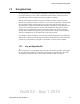

Table Of Contents
- Radio Overview
- Controls & Display
- General Operation
- 3.1 Basic Operation
- 3.1.1 Turning Power ON and Setting Volume
- 3.1.2 Persistent Settings
- 3.1.3 Power-Up Password
- 3.1.4 Speaking into the Microphone
- 3.1.5 Display Backlight Control
- 3.1.6 Display Viewing Angle & Contrast Adjust (Standard Control Head Only)
- 3.1.7 Zone / Channel Display and Select
- 3.1.8 Setting Squelch Control
- 3.1.9 Zone Edit
- 3.1.10 Transmit Disable
- 3.1.11 Operation At Extended Range
- 3.1.12 Preventing Vehicle Battery Discharge
- 3.1.13 Cleaning the Control Head
- 3.1.14 Radio Service
- 3.2 Single Touch
- 3.2.1 Single Touch Buttons
- 3.2.2 Detailed Single Touch Operation
- 3.2.2.1 Conventional Unit Call
- 3.2.2.2 Conventional Call Alert
- 3.2.2.3 Conventional Status
- 3.2.2.4 Conventional Message
- 3.2.2.5 P25 Unit Call
- 3.2.2.6 P25 Call Alert
- 3.2.2.7 P25 Status
- 3.2.2.8 P25 Interconnect
- 3.2.2.9 SNSZ Unit Call
- 3.2.2.10 SNSZ Call Alert
- 3.2.2.11 SNSZ Status
- 3.2.2.12 SNSZ Message:
- 3.2.2.13 SNSZ Interconnect:
- 3.3 Radio Inhibit
- 3.4 Setting Squelch
- 3.5 Operating Modes
- 3.1 Basic Operation
- Radio Wide Features
- 4.1 Option Buttons
- 4.2 Menu Mode
- 4.3 Time-Out Timer
- 4.4 Home Channel Select
- 4.5 Power Output Select
- 4.6 Alert Tone Select
- 4.7 Ignition Power Down Duration
- 4.8 Horn Alert
- 4.9 Microphone Off-Hook Detect
- 4.10 Surveillance Mode
- 4.11 Public Address
- 4.12 Scanning
- 4.13 Scan Lists
- 4.14 Over the Air Programming
- 4.15 Over the Internet Programming
- 4.16 Auto / Unmute
- 4.17 Location Services
- 4.18 Emergency Alarm Receive Indicator
- 4.19 Kiosk Mode
- 4.20 Analog Noise Reduction
- Conventional Mode Features
- 5.1 Monitoring Before Transmitting
- 5.2 Monitor Mode
- 5.3 Busy Channel Lockout
- 5.4 Call Guard Squelch
- 5.5 Penalty Timer
- 5.6 Conversation Timer
- 5.7 Repeater Talk-Around
- 5.8 Displaying Transmit / Receive Frequency
- 5.9 Emergency Alarm and Call
- 5.10 Conventional Mode Channel Scanning
- 5.11 Standard Conventional Calls
- 5.12 DTMF / ANI Signaling
- 5.13 Project 25 Mode Features
- 5.13.1 Digital Unit ID
- 5.13.2 Talkgroup ID
- 5.13.3 Network Access Code (NAC)
- 5.13.4 EFJohnson System Out-of-Range Indicator
- 5.13.5 EFJohnson System Automatic Registration
- 5.13.6 P25 Group Calls
- 5.13.7 P25 Unit Calls
- 5.13.8 P25 Conventional Telephone Calls
- 5.13.9 Call Alert
- 5.13.10 Call History
- 5.13.11 Messaging
- 5.13.12 Status Messaging
- 5.13.13 P25 Packet Data
- 5.14 Keypad Programming
- 5.15 Text Messaging
- SMARTNET / SmartZone / P25 Trunked Features
- 6.1 Analog and Digital Operation
- 6.2 Viewing Unit ID
- 6.3 Standard Group Calls
- 6.4 Unit Calls
- 6.5 Telephone Calls
- 6.6 Call Alert
- 6.7 Messaging
- 6.8 Sending Status Conditions
- 6.9 Emergency Alarm and Call
- 6.10 Failsoft Operation
- 6.11 SMARTNET / SmartZone / P25 Trunking Scanning Features
- 6.12 Dynamic Regrouping
- 6.13 P25 Radio Unit Monitor
- 6.14 SmartZone and P25 Trunking Unique Features
- 6.14.1 Busy Override
- 6.14.2 Site Trunking
- 6.14.3 Determining Current Site and Searching for a New Site
- 6.14.4 Locking / Unlocking a Site
- 6.14.5 Auto Site Search
- 6.14.6 P25 Wide Area Scan
- 6.14.7 Normal P25 and SmartZone Control Channel Hunt
- 6.14.8 Talkgroup Steering through System Access Permissions
- 6.14.9 Radio Information
- 6.14.10 Current Software version in the radio
- 6.15 P25 Trunking System Single Touch
- 6.16 P25 Messaging
- Secure Communication (Encryption)
- Data Features
- Tones & Error Messages
- Service Information

Draft 02 - Sep 1 2015
7-4 Viking Mobile Radio Operating Manual
Secure Communication (Encryption)
7.2.2 PID / SLN Key Management Modes
The channels, talkgroups, and other calls that use encryption are linked to a specific
Physical ID (PID) when the radio is programmed. For example, Zone 1, channel 1 could
be programmed to select the key in PID 1 and Zone 1, channel 2 could select the key in
PID 3. The PID ranges are 0-125 when the PID mode is selected, and 1-126 when the SLN
mode is selected (see Figure 7.1).
Figure 7.1 Key Selection Example
PID or SLN key management modes can be programmed on the Global programming
screen. More information on these modes follows.
PID Mode - When this mode is selected, keys are loaded directly into a PID of 0-125
that corresponds to the PID programmed for each channel (if applicable). Since the
EFJohnson Technologies System Management Assistant (SMA) does not support PID
mode: PID mode can be used only when keys are loaded using the Motorola KVL-3000
or KVL-3000 Plus keyloader.
SLN Mode - The SLN mode must be selected if either Over-The-Air-Rekeying
(OTAR) or the EFJohnson Technologies System Management Assistant (PDA
keyloader) is used. It can also be used if OTAR is not used. SLN mode is digital
encryption, and can also be used with the Motorola KVL-3000, KVL-3000 Plus, and
KVL-4000. With this mode, keys are loaded into a SLN (Storage Location Number),
typically from 0-4095. A Keys Table must then be programmed to link channel PIDs to
a specific SLN.
The use of this type of indirect linking allows keysets and key IDs to be changed
through OTAR while keeping the mapping from the channel or talkgroup the same. For
example, as shown in Figure 7.1, PID 4 selects SLN 24 which selects key slot 24 in both
keysets. This slot contains Key ID 69 in Keyset 1 and Key ID 91 in Keyset 2. Only one
keyset is active at a time. The actual key chosen between these two to transmit with will
depend on which keyset is active, Keyset 1 or Keyset2.
Algorithm ID
Keyset Name (Opt)
SLN 23
SLN 25
Algorithm ID
Keyset Name (Opt)
Key #21: Key ID 54
SLN 24
SLN 22
SLN 21
Keys Table
3
5
4
2
1
PID
Key #22: Key ID 65
Key #23: Key ID 67
Key #24: Key ID 69
Key #25: Key ID 73
Key #25: Key ID 90
Key #24: Key ID 91
Key #23: Key ID 99
Key #22: Key ID 98
Key #21: Key ID 94
Keyset 1
Keyset 2
Zone 1, Chan 2
Zone 2, Chan 4
Zone 2, Chan 5
Zone 3, Chan 1
Zone 3, Chan 2