
Operator's Manual


CIRCUIT DESCRIPTION
4-3
September 2001
Part No. 001-5100-001
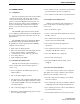
Figure 4-1 Power Supply Diagram
Low Power
Detector
Audio PA
5V Digital
DC/DC
5V Analog
Regulator
Controller
Unswitched
B+
Power
Amplifier
5V
Analog
5 V
Digital
Battery Probe
Transceiver Board
Keypad Board
Digital Board
on/off
Switched RF
B+
The receiver back end consists of a two-pole
crystal filter, IF amplifier, a second two-pole crystal
filter, and the ABACUS digital back-end IC. The two
pole filters are wide enough to accommodate 5 kHz
modulation. Final IF filtering is done digitally in the
ADSIC.
The ABACUS digital back-end chip consists of
an amplifier, second mixer, IF analog-to-digital
converter, a baseband down-converter, and a 2.4 MHz
synthesis circuit to provide a clock to the ADSIC on
the Digital Board. The second LO is generated by
discrete components external to the ABACUS. The
output of the ABACUS is a digital bit stream that is
current driven on a differential pair to reduce noise
generation.
The transmitter consists of an RF power amplifier
IC that amplifies an injection signal from the VCO.
Transmit power is controlled by two custom ICs that
monitor the output of a directional coupler and adjust
the power amplifier control voltages correspondingly.
The signal passes through a Rx/Tx switch that uses
PIN diodes to automatically provide an appropriate
interface to transmit or receive signals.
4.1.5 DIGITAL BOARD
The Digital Board contains the ADSIC, DSP
(TMS320C50), static RAM, FLASH memory, and a
programmable logic IC. The RF Board and Keypad/
Display Board are connected to the Digital Board. The
ADSIC performs the Frequency Discrimination and
receiver filtering functions. It also performs analog-to-
digital (A/D) and digital-to-analog (D/A) conversion.
The DSP performs demodulation and modulation,
voice encoding and decoding, audio filtering, and
squelch signaling. The software for the radio is stored
in FLASH memory that is loaded in to static RAM at
turn-on. The programmable logic IC controls which
device (Flash, SRAM, or UART) is connected to the
DSP address and data bus.
4.1.6 KEYPAD/DISPLAY BOARD
The Keypad Board contains the microcontroller
(HC08), audio circuits, front LCD display assembly,
display driver, and 5V analog and 5V digital regula-
tors. All interfaces to the side connector and the
switches are on this board. The microcontroller deter-
mines transmit/receive frequencies, power levels, and
display content. It communicates with the DSP via a
serial interface.