
User's Manual


INSTALLATION
2-4
May 2000
Part No. 001-2008-204
The operating temperature range is -30°C to
+60°C (-22°F to +140°F), i.e. the same as the repeater.
The fan is thermostatically controlled by the internal
temperature. When the internal heatsink temperature
reaches +45°C (113°F) the fan turns on. When the
heatsink temperature drops below +35°C (95°F) the
fan turns off. If the internal heatsink temperature
reaches +90°C (+194°F) the power supply turns off
until the heatsink temperature drops below +85°C
(+185°F). The over-temperature shutdown and restart
are automatic.
2.7 GROUNDING
CAUTION
PROPER SITE GROUNDING AND LIGHTNING
PROTECTION ARE VERY IMPORTANT TO PRE-
VENT PERMANENT DAMAGE TO THE REPEATER.
As in any fixed radio installation, measures
should be taken to reduce the possibility of lightning
damage to the Viking VX equipment. Proper ground-
ing eliminates shock hazard, protects against electro-
magnetic interference (EMI) and lightning.
Ground each piece of equipment separately. Do
not ground one piece of equipment by connecting it to
another grounded piece of equipment.
A good DC ground must be found or created at
the site. Rooftop site grounds can be researched
through the building management or architects. Tower
site grounds must be made with grounding rods. The
many techniques for providing adequate grounds for
towers and poles and for installing building ground
bus lines are beyond the scope of this manual. Refer
to National Electrical Code article 250 "Grounding
Techniques," article 800 "Communications Systems"
and follow local codes.
The ground bus should be routed to the floor area
within 5 feet of the system with a runner of 6 AWG or
larger solid copper wire or 8 AWG stranded copper
wire.
The outer conductor of each transmission line at
the point where it enters the building should be
grounded using 6 AWG or larger solid copper wire or
8 AWG stranded wire.
Secondary protection (other than grounding) pro-
vides the equipment protection against line transients
that result from lightning. There are two types of sec-
ondary protection, RF and Telephone Line. Use the
same wire sizes as specified for coaxial cables for any
ground connections required by the secondary protec-
tors.
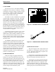
• RF
An RF protector keeps any lightning strike to the
antenna feed line or tower from damaging the Repeat-
ers. Install this protection in-line with the combiner
and antenna feed line.
RF protectors are selected by calculating the
maximum instantaneous voltage at the output of the
combiner. Do this by using the following equation.
where:
V
P
= Voltage at the output of the combiner.
P = repeater output in watts
X= for VSWR=
1.05 1.10 : 1
1.09 1.20 : 1
1.13 1.30 : 1
1.17 1.40 : 1
1.20 1.50 : 1
1.30 1.86 : 1
Example: Repeater power output of 60W with a
VSWR of 1.3 : 1 (for this VSWR, X = 1.13):
V
P
= 87.52V
• Telephone Line
There are four types of protection suppressors for
telephone lines; Gas Tube, Silicon Avalanche Diode,
Metal Oxide Varistor and Hybrid.
The hybrid protector is ideal for Transcrypt Inter-
nation, Inc. equipment, and is strongly recommended.
A hybrid suppressor combines several forms of protec-
tion not available in just one type of device.
Vp 1.414 X() P 50()()=
Vp 1.414 1.13()60 50()()=
Vp 1.59782 60 50()()=
Vp 1.59782 54.772256()=