UNIDOOR PLUS (STYLE I) SHOWER ENCLOSURE GLASS PANEL INSTALLATION INSTRUCTIONS IMPORTANT DreamLine® reserves the right to alter, modify or redesign products at any time without prior notice. For the latest up-to-date technical drawings, manuals, warranty information or additional details please refer to your model’s web page on DreamLine.com Style I Right side panel installation shown STYLE I ATTENTION: This model is also available with the Half Frosted Band glass option.
Style “I”: Half Frosted Band Glass Installation This model features the half frosted glass option. Hinged Left installation shown. To install for hinged Right, flip the door and panels to the proper handing. NOTE: The textured surface of both the stationary glass and door glass should face outside of the shower.
Model#s: Model#s: Model#s: Model#s: SHEN-24290300 SHEN-24290340 SHEN-24295300 SHEN-24295340 SHEN-24300300 SHEN-24300340 SHEN-24305300 SHEN-24305340 SHEN-24310300 SHEN-24310340 SHEN-24315300 SHEN-24315340 SHEN-24320300 SHEN-24320340 SHEN-24325300 SHEN-24325340 SHEN-24330300 SHEN-24330340 SHEN-24335300 SHEN-24335340 SHEN-24340300 SHEN-24340340 SHEN-24345300 SHEN-24345340 SHEN-24350300 SHEN-24350340 SHEN-24355300 SHEN-24355340 SHEN-24360300 SHEN-24360340 SHEN-24365300 SHEN-24365340 SHEN-24290300-HFR SHEN-2
ADDITIONAL MODEL CONFIGURATIONS for UNIDOOR-X GLASS-TO-GLASS HINGE DOORS Model#s: E1230630-## E1230634 E12306530 E12306534 E1233030 E1233034 E12330530 E12330534 E1240630 E1240634 E1243030 E1243034 E1251430 E1251434 E12514530 E12514534 E1261430 E1261434 E12614530 E12614534 E1271430 E1271434 E12714530 E12714534 E1281430 E1281434 E1292230 E1292234 E12922530 E12922534 E1302230 E1302234 E13022530 E13022534 E3270630L E3270630R E3270634L E3270634R E32706530L E32706530R E32706534L E32706534R E3280630L E3280630R
Preparation 1. Prior to installation, examine all boxes and packages for shipping damage and compare the piece count with your packing slip. After opening all boxes and packages read this introduction carefully. Check that all of the needed parts are included in the package by checking off the components on the “Detailed Diagram of Shower Door Components”.
Tools Required Caulk Level Painters Tape Tape Measure Caulk Gun UNIDOOR PLUS (STYLE I) manual Ver 1 Rev 6 10/2016 Electric Drill Pencil Hammer Phillips Screwdriver Mallet Drill bit (Ø=5/16") Wood Drill bit (Ø=1/8") Miter saw 6
Detailed Diagram of Glass Panel Components 9 13 30 23 28 11 19 26 The glass surface with the ClearMax™ label must be installed to face inside of the shower 20 29 29 Packing List 09 11 13 19 20 U-channel 1 (76”, wall profile) Stationary glass Ø5/16” Wall anchor Anti-Water strip (inline panel) Anti-Water strip (enclosure) * 1pc 1pc 14pcs 1pc 1pc 23 26 28 29 30 Countersunk screw ST4.
Style “I”: In-Line Panel with 30”-34” Return Panel Installation NOTE: The Unidoor shower door needs to be installed prior to proceeding with the following Stationary and Return Glass installation instructions. Please see the Single Shower Door installation manual included in the door packaging for complete shower door installation instructions. Before you begin the installation, please recheck your shower opening size. Specific size information can be found using the “SKU TO GLASS SIZE GUIDE” below.
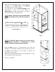
2. Please mark measurement lines on the wall and threshold for the Glass Door and U-channel according to the size of your model. You will need to use the Product Width values determined in step #1 in Size Table A. Please Note that these dimensions are nominal dimensions and not actual glass sizes. " /16 L-1 M NOTE: M and L dimensions are from the finished wall to the outside of the U-channel as shown in Fig. 1.
4. Measure the actual width of your Return panel glass (26) panel. NOTE: You will be doing straight and 45° cuts for this enclosure installation. *All 45° cuts are from the outside dimension. (tip to tip) *It may be necessary to remove any burrs from the cut end of the U-channels with a metal file before placing the Uchannel onto the glass. H Use a miter saw to rough straight cut one of the U-channel 2 (44”, bottom profiles) (29) to the actual width of the glass (+) 11/4”. See Fig. 3 & 4 for details.
Slip the U-channel 2 (bottom profile) back onto the Return panel glass and set the Return panel glass aside. See Fig. 5 for details. 1 2 wall U-channel 1 Return glass U-channel 2 inside 3 4 5 6 inside mark + 1/2" 45° 5. Slip the cut U-channel 2 (44”, bottom profile) (29) and uncut U-channel 1 (76”, wall profile) (09) onto the Return panel glass (26) in the shown locations.
W (+) 1/1 6" NOTE: The top of the Enclosure glass must be level with the Glass door. By using a level across the top of both the In-line Stationary panel glass (11) and door, height differences can be measured. The Adjustment spacers (28) are provided for the Return panel glass (26) only to compensate for such differences by inserting them into the U-Channel 2 (bottom profile) (29). Please use the correct spacer size that is needed for your situation. 45 ° Fig. 7 7.
NOTE: The next step involves careful handling of the glass panels that were just temporarily fixed together to determine a custom fit measurement unique to your installation. It is essential that two installers be used along with responsive communication. Fig. 9 8. Carefully butt the Return panel glass (26) up against the wall vertically according to the M value stated in Size Table A on page 5. Intermittently use a level throughout these steps to ensure that this glass enclosure is leveled properly.
9. Carefully disassemble the panels for the next steps. 90° Corner Bracket See Fig. 11 for details. U-channel 1 Anti-Water strip Return glass Stationary glass U-channel 2 U-channel 2 Painters tape Fig. 11 10. Place the U-Channel 2 (bottom profile) (29) for the Return panel glass (26) onto the threshold base in line with the inside threshold mark. Mark the drill holes on the threshold through the predrilled holes in the UChannel 2 and drill the holes using Ø1/8” drill bit.
Fig. 13 11. Straight cut the U-channel 1 (76”, wall profile) (09) at the top mark that was made in step #8. Place the U-Channel 1 (wall profile) on the U-Channel 2 (bottom profile) (29) and align vertically with the inside wall mark. 1 U-Channel 1 inside outside U-Channel 2 3 Mark the drill holes on the wall through the predrilled holes in the U-Channel 1. Now drill holes in the wall using Ø5/16 drill bit and insert the Ø5/16” Wall anchors (13). 2 4 Ø5/16” 5 See Fig. 14 for details. Fig.
12. Apply waterproof silicone along the bottom surface and around the holes of the UChannel 1 (76”, wall profile) (09). Fasten the U-Channel 1 to the wall with the Countersunk screw ST4.2x40 (23). Insert the provided 2” pieces of the Adjustment Spacers (28) into U-Channel 2 (bottom profile) (29) for minor adjustments if necessary. Apply Waterproof silicone into the groove of both U-Channels. waterproof silicone 1 2 3 4 See Fig. 15 & 16 for details Fig. 15 Fig.
13. Slide the Return panel glass (26) into the groove of both U-Channels. 1 2 NOTE: If you have difficulty sliding the Return panel glass into the U-Channels, you can slightly tap on the Return panel glass with a rubber mallet and a piece of wood. 3 See fig. 17 & 18 for details. Fig. 17 Use Adjustment spacers (#28) as necessary to level your glass Fig.
14. Place the U-Channel 2 (bottom profile) (29) for the Stationary glass (11) onto the threshold base in line with the inside threshold mark and flush with 45° corner cut. Mark the drill holes on the threshold through the predrilled holes in the U-Channel 2 and drill the holes using Ø1/8” drill bit. Apply waterproof silicone along the bottom surface and around the holes of the U- Channel 2 and fasten it to the base with the Countersunk screws ST4.2×40 (23).
15. Apply Waterproof silicone into the groove of the U-Channel 2 (bottom profile) (29) and sparingly along the vertical edge of the Return panel glass (26). waterproof silicone inside See Fig. 21 & 22 for details. outside Fig. 21 Fig.
16. Slide the Stationary glass (11) into the groove of the U-Channel. Make sure the vertical edge of the Stationary glass is flush with outer face of the Return panel glass (26) at the corner. Apply a bead of silicone on the open end of the U-Channel, and its connection. NOTE: If you have difficulty sliding the Stationary glass into the U-Channel, you can slightly tap on the Stationary glass with a rubber mallet and a piece of wood. 1 2 3 4 Fig. 23 See fig. 23 & 24 for details. Fig.
17. Attach the 90° Corner Bracket (30) to the top corner of both glass panels. Ensure that the 90° Corner Bracket is square and gaskets are aligned properly before tightening the glass holding screws. Temporarily secure the corner of the glass panels with several generous strips of Painters tape to keep the corner tight until the silicone cures. See fig. 25 & 26 for details. inside Fig. 25 Fig.
18. Apply waterproof silicone along the connection of all U-Channels to the wall and threshold on the inside of shower. Carefully apply an even bead of silicone down the inside corner of the glass panels. See Fig. 27 & 28 for details. waterproof silicone inside Fig. 27 waterproof silicone inside Fig.
19. Notch the Anti-Water strip (inline panel) (19) 1” at the base to fit around bottom U-channel. Press the Anti-Water strip onto the vertical edge of the Stationary glass (11). 2 1 inside outside See Fig. 29 for details. 4 3 inside inside outside outside Fig.
Product Maintenance BASES and BACKWALLS: To ensure long lasting life for your acrylic back walls: wipe them off after each use with a soft cloth. To clean the acrylic back walls use non-abrasive sprays or cream based cleaners. Avoid the use of aerosol spray cleaners. Never use abrasive cleansers, metal brushes or scrapers that could scratch or dull the surface. GLASS: To ensure long lasting life for your glass shower products: wipe them off after each use with a soft cloth.
TEL: 866-731-2244 FAX: 866-857-3638 DREAMLINE.COM For more information on DreamLine® Shower Doors and Enclosures please visit DreamLine.