
Service Manual


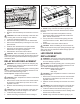


Table Of Contents
- Operation
- Maintenance
- Exploded parts diagram
- Replacement Parts List
- Wiring Diagram
- Preparation for service
- Instructions for removing from wall
- Switchboard Replacement
- Relay Board Replacement
- LED Driver Board Replacement
- AD/DC Adapter Replacement
- Display/Control Board Replacement
- Flicker Motor Replacement
- Flicker Rod Replacement
- LED Light Strips Replacement
- High Temperature Cutout Replacement
- Element Replacement
- Blower/fan Replacement
- Thermistor Replacement
- Troubleshooting Guide

14 www.dimplex.com
THERMISTOR REPLACEMENT
WARNING: Disconnect power before attempting any
maintenance or cleaning to reduce the risk of electric
shock or damage to persons.
CAUTION: If unit was operating prior to servicing allow
at least 10 minutes for lights and heating elements to cool
off to avoid accidental burning of skin.
Tools required: Phillips head screwdriver
Needle nosed pliers
CAUTION: Follow “Preparation for Service” instructions
before proceeding.
1. Remove the decorative glass ember-bed pieces from
the media tray. A medium sized container such as
a bucket or a box will be needed to keep the glass
ember-bed pieces together.
2. Remove the Partially Reective Glass by removing
the 3 screws on each retaining bracket; (2 brackets in
total), located on the left and right side of the Partially
Reective Glass. (Figure 1)
CAUTION: Once the brackets have been removed
ensure that the partially reective glass is held securely to
ensure that it does not fall out of the unit.
3. Attach the provided suction cups to the glass, so that
they can both be easily reached. Holding both suction
cup handles, tilt the glass forward and lift out. Carefully
place the glass aside in a safe location.
4. Remove the left cover panel. The panel is secured to
the unit with two screws on the bottom surface.
5. Locate the thermistor, attached to the standoff secured
to the top panel of the unit and cut the tie wrap to allow
removal of the thermistor from the unit.
6. Loosely wrap the provided tie wrap through the hole in
Top Panel of Unit
Standoff
Tie Wrap
Thermistor
Figure 16
1.5 in.
(3.8 cm)
Figure 15
Left Cover
Panel
Partially
Reective
Glass
Retaining
Brackets
Thermistor
Display / Control
Board
Flame panel
trough
the bottom of the standoff.
7. On the display / control board, disconnect the existing
thermistor, labelled “CNZ-TEMP” and connect the new
thermistor.
8. Run the new thermistor wire to the side of the unit
where the old thermistor was installed, allowing the
wire to sit in the ame panel trough.
9. Feed the thermistor through the tie wrap until the end is
approximately 1.5 in. (3.8 cm) from the top of the unit.
10. Tighten the tie wrap until it is securely holding, not
pinching, the thermistor wire.
11. Reacquire power to the unit to ensure that the new
thermistor is installed correctly, the ambiant temper-
ature will be displayed on the display/control board,
then turn power off.
12. Reassemble the unit in the reverse order.