
Installation Sheet


Page 3
206443 Rev. A
www.specselect.com
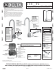
FOR RECESS MOUNT HOUSING: CONTROL BOXES #1 & 8
INSTALLATION AND SET UP INSTRUCTIONS
Installation should be in accordance with local plumbing and electrical codes.
FLUSH ALL PIPES THOROUGHLY BEFORE INSTALLATION.
Control Box #1
Fig. 6
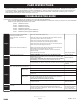
COVERS
060073A
Screws (4/pkg) and driver bit for covers
060577A
12” Stainless Steel Cover
TMV Repair Kits
061137A
Adjustment Wrench
STEP 1. ROUGH IN
STEP 2. FAUCET INSTALLATION
Depending on the installation, use 063160A
thin wall kit OR 063161A thick wall kit (both
provided as standard). Clean surface
where faucet will be mounted. Install
faucet to sink/wall using nut and washer
provided. Ensure gasket is centered on
faucet prior to tightening. Do not over-
tighten the nut or reposition the faucet
once installed, otherwise damage to the
gasket may result. Cutting or trimming
of the gasket is not recommended. If the
gasket is trimmed or modified, then clear
silicone sealant should be used between
the faucet and sink/wall surface to prevent
water leakage.
NOTE: If the gasket is trimmed or not
installed, then use clear silicone
sealant between the faucet and lavatory
to prevent water from leaking beneath
lavatory.
Note: Wires connecting between box(es) and from transformer must be protected from abrasion, and being pulled at connections. They
also may have to be fished through at a later stage of construction. Depending on installation, the cable bushings included may be
replaced by installer supplied 1/2” conduit. Rough-in box as per Figure 8.
The transformer is to be installed in an adjacent accessible space. (Do NOT install the transformer inside the control box.) Cable
from the transformer to the driver board/controller may be roughed in at this time depending on installation. Use cable which complies to
local electrical codes for a 1 amp load. No. 18 is usually sufficient.
HARDWIRE OR BATTERY: If recessed box is supplied, rough in as per Figure 8. The most vandal resistant installation is when the
control box is as close to the bottom of the sink as feasible. For wall hung sink installation, sensor conduit rough in should be directly
under the basin to minimize sensor cord exposure. Rough in drainage. Rough in water supply to 10” control box inlets and to spout
connection. Finish walls.
Valve spacer is for temporary use only for flushing of system. Must be replaced with solenoid valve and washers (Fig. 6 & 7).
Control Box #8
Fig. 7
Tempered Water
(By Others)
Inlet:
1/2” Sweat
060671A
3/4” NPS
Solenoid
Valve &
Washers
061252A
Driver board
to be located
on bracket
063135A
Stop Kit
061252A
Driver
board
to be
located
on
bracket
063135A
Stop Kit
063135A
Stop Kit
Hot Inlet
1/2” Sweat
1/2” Sweat
Outlet
Cold Inlet
1/2” Sweat
063179A
Thermostatic Mixing Valve
with checks & gaskets
1/2” Sweat
Outlet
063164A
Check Valves (2/pkg)