
Installation Sheet


Page 4
206441 Rev. A
FOR RECESS MOUNT HOUSING: CONTROL
BOXES #1 & 8
STEP 3. CONNECT WATER SUPPLY
Install sink and connect drainage to rough in. See applicable
Fig. 6 or Fig. 7. Please note that the connection and fittings
are supplied by the installer to connect 1/2” nominal sweat at
the box outlet and 3/8” compression at the spout. Connect
water supply through to spout. Assure supply lines are
completely flushed and free of debris.
STEP 4. FLUSH SYSTEM/SET TEMPERATURE
Remove coverplate from control box. Open screwdriver stop(s)
to flush installation for 1 minute minimum.
4A
Run water for a sufficient time so the hot and cold water
supplies are as hot and cold as they will get.
4B Place a thermometer in a plastic container and hold in the
water stream. Record the temperature reading and note
position of temperature control, and lock at desired setting.
4C
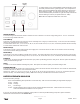
Thermostatic Mixing Valve (Fig. 7) To adjust the mixed
outlet temperature of the valve, remove the cap to gain
access to the adjusting spindle. The spindle should be
rotated towards the “C” side to reduce the temperature and
towards the “H” side to increase the temperature - until the
desired set point is reached (refer to Fig. 9).
Periodic Inspection/Maintenance - We recommend that
this valve is checked at least once per year to ensure its
continued function. For installations with poor or unknown
water quality, or other adverse supply conditions, it may be
necessary to check the valve at more frequent intervals.
The temperature should be checked at the same outlet as
was used for commissioning in the first instance. If the
temperature is more than 3°F from the commissioning in temperature, refer to the included
Cash Acme Maintenance and Installation Guide.
4D Close stop(s).
STEP 5. CONNECT ELECTRICAL SUPPLY, SOLENOID VALVE AND SENSOR
Remove plastic threaded spacer nipple and install solenoid valve with body arrow in the
direction of water flow. See Fig. 10. Feed sensor wire from spout into control box and then
connect to the driver board. Connect red solenoid wire from the driver board to “+” marked
solenoid terminal on solenoid valve, black solenoid wire to other solenoid terminal.
BATTERY VERSION Install four “Alkaline C” batteries provided into the battery holder. Connect
battery clip from the driver board to battery pack. Ensure snap does not touch any conductive
metal surface. Two beeps indicate power is ready for use. Use caution not to damage wires or
components on electronic driver board. Secure cover using screws. Do not use 9V battery.
HARDWIRE VERSION Install CSA and/or UL approved Class 2 transformer or equivalent in a
convenient location or in a pipe chase. (Do NOT install the transformer inside the control
box.)
With the power off, bring the 24 VAC supply wires into the box. Connect the 24 VAC supply to
the 060683A conversion kit. Connect the battery snap of the hardwire converter to the driver
board battery clip. Ensure snap does not touch any conductive metal surface. Turn on power
supply for the transformer. Secure cover using screws. Do not remove battery snap from
hardwire converter by using a flat screwdriver, damage may result.
STEP 6. SERVICES
Open screwdriver stop(s). Flush line. Install aerator.
Cover
Fig. 10
Valve
Spacer
(Replace
with
Solenoid
Valve &
Washers
after system
is flushed)
Solenoid Valve
(INSTALL:
replacing
SPACER after
system is
flushed.)
SOLENOID
may be
ROTATED to
ALLOW for installation
of COVER ASSEMBLY.
Sensor
Watertight
Connector
Flexible Sensor
Cord Conduit
257mm (10.13")
Control Box
305mm (12")
Stainless Steel
Cover Plate
102mm (4")
Coverplate
355mm
(14”)
max.
Product supplied
as shown by solid
lines. All items
shown by dotted
lines supplied by
others.
Typical Installation
(Recessed Mount Box)
Fig. 8
Gooseneck
Spout
INSTALLATION AND SET UP INSTRUCTIONS
www.specselect.com
Connection
and Fittings
by Installer
Fig. 9
Towards
“H” side to
increase
temperature
Towards
“C” side
to reduce
temperature