
Integration Guide

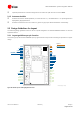


Table Of Contents
- Preface
- Contents
- 1 System description
- 1.1 Overview
- 1.2 Architecture
- 1.3 Pin-out
- 1.4 Operating modes
- 1.5 Power management
- 1.6 System functions
- 1.7 RF connection
- 1.8 SIM interface
- 1.9 Serial Communication
- 1.10 Audio
- 1.11 ADC input (LEON-G100 only)
- 1.12 General Purpose Input/Output (GPIO)
- 1.13 M2M Setup Schematic Example
- 1.14 Approvals
- 2 Design-In
- 3 Handling and soldering
- 4 Product Testing
- Appendix
- A Extra Features
- B Glossary
- Related documents
- Revision history
- Contact

LEON-G100/G200 - System Integration Manual
GSM.G1-HW-09002-F3 Preliminary Design-In
Page 75 of 101
VCC connection may carry a maximum burst current in the order of 2.5 A. Therefore, it is typically
implemented as a wide PCB line with short routing from DC supply (DC-DC regulator, battery pack, etc)
The module automatically initiates an emergency shutdown if supply voltage drops below hardware
threshold. In addition, reduced supply voltage can set a worst case operation point for RF circuitry that may
behave incorrectly. It follows that each voltage drop in the DC supply track will restrict the operating margin
at the main DC source output. Therefore, the PCB connection has to exhibit a minimum or zero voltage
drop. Avoid any series component with Equivalent Series Resistance (ESR) greater than a few mΩ
Given the large burst current, VCC line is a source of disturbance for other signals. Therefore route VCC
through a PCB area separated from sensitive analog signals. Typically it is good practice to interpose at least
one layer of PCB ground between VCC track and other signal routing
The VCC supply current supply flows back to main DC source through GND as ground current: provide
adequate return path with suitable uninterrupted ground plane to main DC source
A tank capacitor with low ESR is often used to smooth current spikes. This is most effective when placed as
close as possible to VCC. From main DC source, first connect the capacitor and then VCC. If the main DC
source is a switching DC-DC converter, place the large capacitor close to the DC-DC output and minimize
the VCC track length. Otherwise consider using separate capacitors for DC-DC converter and
LEON-G100/G200 tank capacitor. Note that the capacitor voltage rating may be adequate to withstand the
charger over-voltage if battery-pack is used
VCC is directly connected to the RF power amplifier. Add capacitor in the pF range from VCC to GND along
the supply path
Since VCC is directly connected to RF Power Amplifier, voltage ripple at high frequency may result in
unwanted spurious modulation of transmitter RF signal. This is especially seen with switching DC-DC
converters, in which case it is better to select the highest operating frequency for the switcher and add a
large L-C filter before connecting to LEON-G100/G200 in the worst case
The large current generates a magnetic field that is not well isolated by PCB ground layers and which may
interact with other analog modules (e.g. VCO) even if placed on opposite side of PCB. In this case route VCC
away from other sensitive functional units
The typical GSM burst has a periodic nature of approx. 217 Hz, which lies in the audible audio range. Avoid
coupling between VCC and audio lines (especially microphone inputs)
If VCC is protected by transient voltage suppressor / reverse polarity protection diode to ensure that the
voltage maximum ratings are not exceeded, place the protecting device along the path from the DC source
toward LEON-G100/G200, preferably closer to the DC source (otherwise functionality may be compromised)
VCC pad is longer than other pads, and requires a “No-Routing” area for any other signals on the top layer
of the application board PCB, below the LEON-G100/G200
VCC line should be wide and short.
Route away from sensitive analog signals.
2.2.1.3 Analog Audio
Accurate analog audio design is very important to obtain clear and high quality audio. The GSM signal burst has
a repetition rate of 271 Hz that lies in the audible range. A careful layout is required to reduce the risk of noise
pickup from audio lines due to both VCC burst noise coupling and RF detection.
Analog audio is separated in the two paths:
1. Audio Input (uplink path): MIC_BIASx, MIC_GNDx
2. Audio Outputs (downlink path): SPK_P / SPK_N, HS_P
The most sensitive is the uplink path, since the analog input signals are in the µV range. The two microphone
inputs have the same electrical characteristics, and it is recommended to implement their layout with the same
routing rules.