
Users Guide


452 | OSPFv2 Dell PowerConnect ArubaOS 5.0 | [User Guide
WLAN Topology
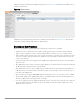
The controller (Figure 98) is configured with VLAN 10 and VLAN 12 as user VLANs. These VLANs have clients
on the subnets and the controller is the default router for those clients. VLAN 4 and VLAN 5 both have OSPF
enabled. These interfaces are connected to a upstream routers (Router 1 and Router 2). The OSPF interface cost
on VLAN 4 is configured lower than VLAN 5. The IDs are:
z Dell controller—40.1.1.1
z Router 1—50.1.1.1
z Router 2—60.1.1.1
Figure 98 WLAN OSPF Topology
Based on the cost of the uplink interface, default route from one of the upstream routers is installed in the
forwarding information base (FIB) by the routing information base/route table manager (RIB/RTM) module.
WLAN Routing Table
View the controller routing table using the show ip route command:
(host) #show ip route
Codes: C - connected, O - OSPF, R - RIP, S - static
M - mgmt, U - route usable, * - candidate default
Gateway of last resort is 4.1.1.2 to network 0.0.0.0
O* 0.0.0.0/0 [1/0] via 4.1.1.2*
C 4.1.1.0 is directly connected, VLAN4
C 5.1.1.0 is directly connected, VLAN5
C 10.1.1.0 is directly connected, VLAN10
C 12.0.1.0 is directly connected, VLAN12
Below is the routing table for Router 1:
(router1) #show ip route
Codes: C - connected, O - OSPF, R - RIP, S - static
M - mgmt, U - route usable, * - candidate default
O 10.1.1.0/24 [1/0] via 4.1.1.1
O 12.1.1.0/24 [1/0] via 4.1.1.1
C 4.1.1.0 is directly connected, VLAN4
OSPF_002
Router 1
50.1.1.1
Router 2
60.1.1.1
Dell
Controller
40.1.1.1
4.1.1.2/24
VLAN 4: 4.1.1.1/24
VLAN 5: 5.1.1.1/24
VLAN 10: 10.1.1.1/24
VLAN 12: 12.1.1.1/24
5.1.1.2/24