
Owners Manual


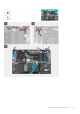


Table Of Contents
- Vostro 14 5410 Service Manual
- Working on your computer
- Removing and installing components
- Recommended tools
- Screw list
- Major components of your system
- Base cover
- Battery
- Memory module
- Solid-state drive
- Wireless card
- Fan
- Coin-cell battery
- Heat sink
- Network-port bracket
- I/O board
- Speakers
- Touchpad
- Display assembly
- Power button with optional fingerprint reader
- Power-adapter port
- System board
- Palm-rest and keyboard assembly
- Drivers and downloads
- System setup
- Troubleshooting
- Getting help

Steps
1. Peel the tape that secures the display-cable connector latch to the system board.
2. Lift the latch and disconnect the display-cable from the connector on the system board.
3. Remove the two screws (M2.5x5) that secure the right-display hinge to the system board.
4. Pry open the right-display hinge at an angle of 90 degrees.
5. Remove the two screws (M2.5x5) that secure the left-display hinge to the I/O board.
6. Pry open the left-display hinge at an angle of 90 degrees.
7. Gently lift the palm-rest and keyboard assembly off the display assembly
CAUTION:
To avoid damaging the display, do not slide the palm-rest and keyboard assembly over the display
assembly.
Installing the display assembly
Prerequisites
If you are replacing a component, remove the existing component before performing the installation process.
About this task
The following image(s) indicate the location of the display assembly and provides a visual representation of the installation
procedure.
46
Removing and installing components