The lightning flash with arrowhead symbol within an equilateral triangle is intended to alert the user to the presence of uninsulated "dangerous voltage" within the product's enclosure, that may be of sufficient magnitude to constitute a risk of electric shock to persons. The exclamation point within an equilateral triangle is intended to alert the user to the presence of important operating and maintenance (servicing) instructions in the literature accompanying the appliance.
1. Introduzione Congratulazioni per l'acquisto del sistema di diffusione T5SA! Per un impiego corretto del sistema seguite le istruzioni riportate in questo manuale. Buon divertimento e buon lavoro! 2. Sommario 4. Il sistema T5SA (fig. 1) 3. Norme di Installazione e Uso . . . . . . . . . . 3 1. La protezione e la manutenzione . . . . . . . . . . . . 2. Prevenzione di possibili disturbi . . . . . . . . . . . . . 3. Collegamenti . . . . . . . . . . . . . . . . . . . . . . . . . . . . 4.
IMPORTANTE!!! Le uscite del T5SA (LINK) rilanciano verso l’esterno lo stesso segnale presente in ingresso. Pertanto, nel caso si utilizzi il sub-woofer con la d400 ed i diffusori della serie TITANIUM, è il processore digitale contenuto nei satelliti che provvede a filtrare le basse frequenze. Nel caso, invece, si utilizzino come satelliti altri diffusori non dotati di processore interno, è necessario provvedere a filtrare le basse frequenze tramite un crossover esterno. 5. Installazione e collegamenti 1.
02. d400 HOUSE: derivato dal precedente, include l’utilizzo del MULTICOMP per enfatizzare le frequenza basse al di sotto dei 60Hz. Particolarmente adatto alla riproduzione della musica house e dance in genere. 03. 2xT3A + 2xT5SA: da utilizzare in un sistema STEREO comprendente due diffusori T3A come satelliti e due T5SA come sub-woofer (vedi paragrafo 2. Collegamenti e fig. 4a). 04.
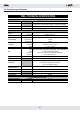
10. Specifiche tecniche T5SA • SPECIFICHE TECNICHE SPECIFICHE del DIFFUSORE Componenti Woofer da 15" Multistrato con vernice nera antigraffio - Griglia metallica di protezione Maniglie ed adattatore in metallo - 4 ruote per il trasposrto 466x600x600 43.
1. Introduction Congratulations for having chosen the T5SA loudspeaker system! To make the best use of the system, please read this manual thoroughly before operating the equipment. 2. Contents 3. Instructions for use and installation . . . 7 1. Protection and maintenance . . . . . . . . . . . . . . . . 2. Prevention of possible interference . . . . . . . . . . . 3. Connections . . . . . . . . . . . . . . . . . . . . . . . . . . . . . 4. Connector cables . . . . . . . . . . . . . . . . . . . . . . . . .
IMPORTANT!!! The T5SA outputs (LINK) send out the same signal received on the inputs. If you use the sub-woofer together with the d400 or one of the TITANIUM series loudspeakers, the processor included in the satellites filters the low frequencies. If you use instead as satellites loudspeakers from other brands, not provided with a built-in processor, you need to filter the low frequencies using an external crossover. 5. Installation and connections 1. Installation (fig.
04. 2xT3A + 1xT5SA: to be used in a STEREO system two T3A loudspeakers as satellites and one T5SA as sub-woofer (see chapter 2. Connections and fig. 4b). This PRESET is derived from the previous one with a level reduction and the use of a different crossover filter. 05. T4A: for the use of the sub-woofer together with the T4A loudspeaker system. 06. T4A HOUSE: derived from the previous one, includes the use of the MULTICOMP to enhance the frequencies below 60Hz.
. Technical specifications T5SA • TECHNICAL SPECIFICATIONS LOUDSPEAKER SPECIFICATIONS Components 15" woofer Laminated birch plywood with black scratch-resistant paint - Metal grid Metal handles and speaker stand adapter - 4 wheels for trasportation 466x600x600 43.
FIG.
FIG. 2 - DPPM BLOCK DIAGRAM FIG.
FIG. 4 - CONNECTIONS FIG. 4a FIG.
FIG.
FIG.
FIG.
FEDERAL COMMUNICATIONS COMMISSION NOTE: This equipment has been tested and found to comply with the limits for a Class A digital device, pursuant to Part 15 of FCC Rules. These limits are designed to provide reasonable protection against harmful interference when the equipment is operated in a commercial environment.