Dell Precision M2800 擁有者手冊 管制型號: P29F 管制類型: P29F001
註、警示與警告 註: 「註」表示可以幫助您更有效地使用電腦的重要資訊。 警示: 「警示」表示有可能會損壞硬體或導致資料遺失,並告訴您如何避免發生此類問題。 警告: 「警告」表示有可能會導致財產損失、人身傷害甚至死亡。 Copyright © 2014 Dell Inc. 著作權所有,並保留一切權利。本產品受美國與國際著作權及智慧財產權法保護。Dell™ 與 Dell 徽標是 Dell Inc. 在美國和/或其他轄區的商標。本文提及的所有其他標誌與名稱皆屬於其個別公司的商標。 2014 -10 Rev.
目錄 1 拆裝電腦...................................................................................................................6 拆裝電腦內部元件之前........................................................................................................................... 6 關閉電腦................................................................................................................................................. 7 拆裝電腦內部元件之後........................................................................................
安裝處理器........................................................................................................................................... 26 卸下鍵盤...............................................................................................................................................26 安裝鍵盤............................................................................................................................................... 27 卸下手掌墊組件........................................................
技術規格................................................................................................................ 66 6 與 Dell 公司聯絡...................................................................................................
1 拆裝電腦 拆裝電腦內部元件之前 請遵守以下安全規範,以避免電腦受到可能的損壞,並確保您的人身安全。除非另有說明,否則本文件中的每 項程序均假定已執行下列作業: • 您已閱讀電腦隨附的安全資訊。 • 按相反的順序執行卸下程序可以裝回或安裝 (當元件為單獨購買時) 元件。 警告: 打開電腦護蓋或面板之前,請先斷開所有電源。拆裝電腦內部元件之後,請先裝回所有護蓋、面板 和螺絲,然後再連接電源。 警告: 拆裝電腦內部元件之前,請先閱讀電腦隨附的安全資訊。如需更多安全最佳實務資訊,請參閱 Regulatory Compliance (法規遵循) 首頁:www.dell.
9. 打開顯示器。 10. 按電源按鈕,以導去主機板上的剩餘電量。 警示: 為防止觸電,在打開機箱蓋之前,請務必從電源插座上拔下電腦電源線。 警示: 在觸摸電腦內部的任何元件之前,請觸摸未上漆的金屬表面 (例如電腦背面的金屬),以確保接 地並導去您身上的靜電。作業過程中,應經常碰觸未上漆的金屬表面,以導去可能損壞內部元件的 靜電。 11. 從對應的插槽中取出所有已安裝的 ExpressCard 或智慧卡。 關閉電腦 警示: 為避免遺失資料,請在關閉電腦之前儲存並關閉所有開啟的檔案,結束所有開啟的程式。 1. 關閉作業系統: • 在 Windows 8 中: – – • 使用觸控裝置: a. 從螢幕右緣向內掃動,以開啟快速鍵功能表,然後選擇設定。 b. 選擇 然後選擇關機 使用滑鼠: a. 將游標指向螢幕右上角,然後按一下設定。 b. 按一下 然後選擇關機。 在 Windows 7 中: 1. 按一下開始 2. 按一下關機。 。 或 2. 1. 按一下開始 2.
警示: 若要連接網路纜線,請先將網路纜線插入網路裝置,然後再將其插入電腦。 3. 裝回電池。 4. 將電腦和所有連接裝置連接至電源插座。 5.
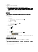
2 卸下和安裝元件 本節說明如何從電腦卸下或安裝元件的詳細資訊。 建議的工具 本文件中的程序可能需要以下工具: • 小型平頭螺絲起子 • 十字槽螺絲起子 • 小型塑膠畫線器 系統概觀 圖 1. 後視圖 — 後蓋已卸下 1. 散熱器組件 2. 硬碟機 3. 記憶體 4.
5. ExpressCard 插槽 6. 光碟機 7. 幣式電池 8. 基座角蓋 (左側) 9. WWAN 卡 10. WLAN 卡 11. 擴充基座連接埠 12. 電池凹槽 13. 基座角蓋 (右側) 圖 2. 頂視圖 — 鍵盤和手掌墊組件已卸下 1. WiFi 開關板 2. 喇叭 3. ExpressCard 插槽卡 4. 主機板 5. 喇叭 6. 硬碟機凹槽 7. VGA 板 8. 顯示器組件 卸下 Secure Digital (SD) 卡 1. 按照拆裝電腦內部元件之前中的程序進行操作。 2.
安裝 Secure Digital (SD) 卡 1. 將 SD 卡推入插槽直到它卡至定位。 2. 按照拆裝電腦內部元件之後中的程序進行操作。 卸下 ExpressCard 1. 按照拆裝電腦內部元件之前中的程序進行操作。 2. 向裡按一下 ExpressCard,以將其從電腦中彈出,然後從電腦中取出 ExpressCard。 安裝 ExpressCard 1. 將 ExpressCard 推入其插槽,直至它卡入到位。 2. 按照拆裝電腦內部元件之後中的程序進行操作。 卸下電池 1. 按照拆裝電腦內部元件之前中的程序進行操作。 2.
3.
安裝電池 1. 將電池滑入其插槽,直至其卡入到位。 2. 按照拆裝電腦內部元件之後中的程序進行操作。 卸下基座護蓋 1. 按照拆裝電腦內部元件之前中的程序進行操作。 2.
3.
安裝基座護蓋 1. 放置基座護蓋,對準電腦的螺絲孔。 2. 鎖緊將基座護蓋固定在電腦上的螺絲。 3. 安裝電池。 4. 按照拆裝電腦內部元件之後中的程序進行操作。 拆卸基座角蓋 1. 按照拆裝電腦內部元件之前中的程序進行操作。 2. 卸下電池。 3. 卸下基座護蓋。 4.
5. 卸下固定右側基座角蓋的螺絲,將它從電腦抬起卸下。 安裝基座角蓋 1. 安裝左側和右側基座角蓋,並對準電腦上的螺絲孔。 2. 鎖緊將基座角蓋固定在電腦上的螺絲。 3. 安裝: a. 基座護蓋 b. 電池 4. 按照拆裝電腦內部元件之後中的程序進行操作。 卸下記憶體 1. 按照拆裝電腦內部元件之前中的程序進行操作。 2. 卸下: a. 電池 b.
3. 從記憶體模組撬開固定夾,直到它彈出為止,然後將記憶體模組從主機板上的連接器抬起取出。 安裝記憶體 1. 將記憶體插入記憶體插槽。 2. 壓下固定夾,將記憶體模組固定至主機板。 3. 安裝: a. 基座護蓋 b. 電池 4. 按照拆裝電腦內部元件之後中的程序進行操作。 卸下硬碟機 1. 按照拆裝電腦內部元件之前中的程序進行操作。 2. 卸下電池。 3. 卸下將硬碟機固定至電腦的螺絲。將硬碟機推出電腦。 4.
5. 鬆開硬碟機隔離卡。將硬碟機隔離卡從硬碟機撕下。 安裝硬碟機 1. 將硬碟機隔離卡安裝至硬碟機。 2. 將硬碟機貯存盒附接至硬碟機。 3. 旋緊用來將硬碟機貯存盒固定至硬碟機的螺絲。 4. 將硬碟機滑入電腦。 5. 旋緊用來將硬碟機固定至電腦的螺絲。 6. 安裝電池。 7. 按照拆裝電腦內部元件之後中的程序進行操作。 卸下光碟機 1. 按照拆裝電腦內部元件之前中的程序進行操作。 2. 卸下電池。 3.
4. 卸下將光碟機閂鎖固定至光碟機的螺絲。推動光碟機閂鎖並將它從光碟機卸下。 5. 卸下將光碟機閂鎖托架固定至光碟機的螺絲。將光碟機閂鎖托架從光碟機卸下。 安裝光碟機 1. 將光碟機閂鎖托架對準其在光碟機上的位置。 2. 旋緊將光碟機閂鎖托架固定至光碟機的螺絲。 3. 將光碟機閂鎖推入光碟機閂鎖托架。 4. 旋緊將光碟機閂鎖固定至光碟機閂鎖托架的螺絲。 5. 將光碟機推入磁碟機支架。 6.
7. 安裝電池。 8. 按照拆裝電腦內部元件之後中的程序進行操作。 卸下無線區域網路 (WLAN) 卡 1. 按照拆裝電腦內部元件之前中的程序進行操作。 2. 卸下: a. 電池 b. 基座護蓋 3. 中斷連接天線纜線,卸下將 WLAN 卡固定至主機板的螺絲,然後將 WLAN 卡從電腦卸下。 安裝 WLAN 卡 1. 將 WLAN 卡以 45 度角插入其插槽中。 2. 鎖緊螺絲,將 WLAN 卡固定在電腦上。 3. 將天線纜線分別連接至 WLAN 卡上標示的連接器。 4. 安裝: a. 基座護蓋 b. 電池 5. 按照拆裝電腦內部元件之後中的程序進行操作。 卸下無線廣域網路 (WWAN) 卡 1. 按照拆裝電腦內部元件之前中的程序進行操作。 2. 卸下: a. 電池 b. 基座護蓋 3. 執行以下步驟,如圖所示: a. 從 WWAN 卡拔下天線纜線。 b. 卸下將 WWAN 卡固定至電腦的螺絲。 c.
安裝 WWAN 卡 1. 將 WWAN 卡置於主機板的插槽。 2. 壓下 WWAN 卡並鎖緊將 WWAN 卡固定至電腦的螺絲。 3. 將天線纜線連接至 WWAN 卡上的對應連接器。 4. 安裝: a. 基座護蓋 b. 電池 5. 按照拆裝電腦內部元件之後中的程序進行操作。 卸下網路連接器 1. 按照拆裝電腦內部元件之前中的程序進行操作。 2. 卸下: a. 電池 b. 基座護蓋 c. 基座角蓋 (左側) 3. 執行以下步驟,如圖所示: a. 從主機板拔下纜線。 b. 將纜線從固定導軌鬆開。 c. 卸下將網路連接器托架固定至電腦的螺絲。 4.
安裝網路連接器 1. 將網路連接器對齊其在電腦上的位置。 2. 將網路連接器托架置於網路連接器上。 3. 旋緊將網路連接器托架固定至電腦的螺絲。 4. 將纜線穿入固定導軌。 5. 將纜線連接至主機板。 6. 安裝: a. 基座角蓋 (左側) b. 基座護蓋 c. 電池 7. 按照拆裝電腦內部元件之後中的程序進行操作。 卸下幣式電池 1. 按照拆裝電腦內部元件之前中的程序進行操作。 2. 卸下: a. 電池 b. 基座護蓋 3.
安裝幣式電池 1. 將幣式電池裝入其插槽內。 2. 將幣式電池纜線連接至主機板。 3. 安裝: a. 基座護蓋 b. 電池 4. 按照拆裝電腦內部元件之後中的程序進行操作。 卸下電源連接器 1. 按照拆裝電腦內部元件之前中的程序進行操作。 2. 卸下: a. 電池 b. 基座角蓋 (右側) c. 基座護蓋 3. 執行以下步驟,如圖所示: a. 從主機板拔下電源連接器纜線。 b. 從固定導軌鬆開電源連接器纜線。 c. 卸下將電源連接器托架固定至電腦的螺絲。 4.
安裝電源連接器 1. 將電源連接器對準裝至其在電腦中的位置。 2. 將電源連接器托架置於電源連接器上。 3. 鎖緊將電源連接器托架固定至電腦的螺絲。 4. 將纜線穿入固定導軌。 5. 將纜線連接至主機板。 6. 安裝: a. 基座護蓋 b. 基座角蓋 (右側) c. 電池 7. 按照拆裝電腦內部元件之後中的程序進行操作。 卸下散熱器組件 1. 按照拆裝電腦內部元件之前中的程序進行操作。 2. 卸下: a. 電池 b. 基座護蓋 3.
4. 執行以下步驟,如圖所示: a. 推出散熱器組件。 b. 將散熱器組件從電腦抬出。 安裝散熱器組件 1. 將散熱器組件推至其在主機板上的位置。 2. 旋緊用來將散熱器組件固定至主機板的螺絲。 3. 將風扇纜線連接至主機板。 4. 安裝: a. 基座護蓋 b. 電池 5. 按照拆裝電腦內部元件之後中的程序進行操作。 卸下處理器 1. 按照拆裝電腦內部元件之前中的程序進行操作。 2. 卸下: a. 電池 b. 基座護蓋 c. 散熱器 3.
安裝處理器 1. 將處理器的槽口對準插槽,並將處理器插入插槽中。 2. 沿順時針方向轉動處理器凸輪鎖。 3. 安裝: a. 散熱器 b. 基座護蓋 c. 電池 4. 按照拆裝電腦內部元件之後中的程序進行操作。 卸下鍵盤 1. 按照拆裝電腦內部元件之前中的程序進行操作。 2. 卸下電池。 3. 從鍵盤邊緣撬起鍵盤邊條,然後從電腦卸下鍵盤邊條。 4.
5. 翻轉鍵盤,將鍵盤纜線從主機板拔下。 安裝鍵盤 1. 將鍵盤纜線連接至主機板。 2. 將鍵盤安置且對齊在電腦的螺絲插座。 3. 旋緊將鍵盤固定至手掌墊組件的螺絲。 4. 將鍵盤邊條插入鍵盤,並沿著邊緣壓下,使之卡入定位。 5. 安裝電池。 6. 按照拆裝電腦內部元件之後中的程序進行操作。 卸下手掌墊組件 1. 按照拆裝電腦內部元件之前中的程序進行操作。 2. 卸下: a. b. c. d. e.
f. 基座護蓋 g. 基座角蓋 3. 卸下用來將手掌墊組件固定至電腦底座的螺絲。 4.
5. 拔下以下纜線: a. 指紋掃描器 b. 觸控墊 c.
6.
安裝手掌墊組件 1. 將手掌墊組件對準電腦中原來的位置,然後將它卡入定位。 2. 旋緊用來將手掌墊組件固定至電腦的螺絲。 3. 連接以下纜線: a. 電源按鈕 b. 觸控墊 c. 指紋掃描器 4. 翻轉電腦,然後卸下將手掌墊組件固定至電腦底座的螺絲。 5. 安裝: a. b. c. d. e. f. g. 6.
卸下 WiFi 開關板 1. 按照拆裝電腦內部元件之前中的程序進行操作。 2. 卸下: a. b. c. d. e. f. g. h. 3. SD 卡 ExpressCard 電池 鍵盤 顯示器鉸接蓋 基座護蓋 基座角蓋 手掌墊組件 執行以下步驟,如圖所示: a. 從主機板拔下纜線。 b. 卸下用來固定 WiFi 開關板的螺絲,然後將電腦抬起取出。 安裝 WiFi 開關板 1. 將 WiFi 開關板置入其凹槽內。 2. 旋緊將 WiFi 開關板固定至電腦的螺絲。 3. 將纜線連接至主機板。 4. 安裝: a. b. c. d. e. f. g. h. 5.
卸下 VGA 板 1. 按照拆裝電腦內部元件之前中的程序進行操作。 2. 卸下: a. b. c. d. e. f. g. h. 3. SD 卡 ExpressCard 電池 鍵盤 顯示器鉸接蓋 基座護蓋 基座角蓋 手掌墊組件 卸下將 VGA 板固定至電腦的螺絲,然後將它從其連接器卸下。 安裝 VGA 板 1. 將 VGA 板插入其插槽 2. 鎖緊將 VGA 板固定至電腦的螺絲。 3. 安裝: a. b. c. d. e. f. g. h. 4. 手掌墊組件 基座角蓋 基座護蓋 顯示器鉸接蓋 鍵盤 電池 ExpressCard SD 卡 按照拆裝電腦內部元件之後中的程序進行操作。 卸下 ExpressCard 插槽卡 1. 按照拆裝電腦內部元件之前中的程序進行操作。 2.
a. b. c. d. e. f. g. h. 3. SD 卡 ExpressCard 電池 鍵盤 顯示器鉸接蓋 基座護蓋 基座角蓋 手掌墊組件 卸下將 ExpressCard 插槽卡固定在電腦上的螺絲。將 ExpressCard 插槽卡從電腦中卸下。 安裝 ExpressCard 插槽卡 1. 將 ExpressCard 插槽卡置於其插槽中。 2. 旋緊用來將 ExpressCard 插槽卡固定至電腦的螺絲。 3. 安裝: a. b. c. d. e. f. g. h. 4. 手掌墊組件 基座角蓋 基座護蓋 顯示器鉸接蓋 鍵盤 電池 ExpressCard SD 卡 按照拆裝電腦內部元件之後中的程序進行操作。 卸下主機板 1. 按照拆裝電腦內部元件之前中的程序進行操作。 2. 卸下: a. b. c. d. e.
f. g. h. i. j. k. l. m. n. o. p. q. r. 3. 光碟機 顯示器鉸接蓋 基座護蓋 基座角蓋 電源連接器 幣式電池 記憶體 WLAN 卡 WWAN 卡 散熱器 處理器 VGA 板 ExpressCard 插槽卡 執行以下步驟,如圖所示: a. 從主機板中斷連接 WiFi 開關。 b. 從主機板中斷連接喇叭纜線: 4.
5.
安裝主機板 1. 將主機板對準電腦上的連接埠。 2. 鎖緊用來固定主機板的螺絲。 3. 將以下纜線連接至主機板: a. 喇叭 b. WiFi 開關 4. 安裝: a. b. c. d. e. f. g. h. i. j. k. l.
m. n. o. p. q. r. 5. 光碟機 硬碟機 鍵盤 電池 ExpressCard SD 卡 按照拆裝電腦內部元件之後中的程序進行操作。 卸下喇叭 1. 按照拆裝電腦內部元件之前中的程序進行操作。 2. 卸下: a. b. c. d. e. f. g. h. i. j. k. l. m. n. o. p. q. r. s. t. 3.
4.
安裝喇叭 1. 將喇叭對準置於其在電腦中的位置,然後將喇叭纜線裝入電腦的固定導軌。 2. 鎖緊用來固定喇叭的螺絲。 3. 安裝: a. b. c. d. e. f. g. h. i. j. k. l. m. n. o. p.
q. r. s. t. 4. 鍵盤 電池 ExpressCard SD 卡 按照拆裝電腦內部元件之後中的程序進行操作。 卸下顯示器鉸接蓋 1. 按照拆裝電腦內部元件之前中的程序進行操作。 2. 卸下電池。 3. 卸下將顯示器鉸接蓋固定至電腦的螺絲,然後將顯示器鉸接蓋從電腦卸下。 安裝顯示器鉸接蓋 1. 將顯示器鉸接蓋對準螺絲孔。 2. 旋緊用來將顯示器鉸接蓋固定至電腦的螺絲。 3. 安裝電池。 4. 按照拆裝電腦內部元件之後中的程序進行操作。 卸下顯示器組件 1. 按照拆裝電腦內部元件之前中的程序進行操作。 2. 卸下: a. b. c. d. 3.
4.
5.
6.
安裝顯示器組件 1. 將顯示器組件置於其在電腦上的位置。 2. 鎖緊用來固定顯示器組件的螺絲。 3. 將 LVDS 纜線和攝影機纜線穿入固定導軌。 4. 將天線纜線穿過繞線通道。 5. 將天線纜線連接至電腦上的 WLAN 卡。 6. 將攝影機纜線連接至電腦。 7. 安裝: a. b. c. d. 8. 基座角蓋 基座護蓋 顯示器鉸接蓋 電池 按照拆裝電腦內部元件之後中的程序進行操作。 卸下顯示器前蓋 1. 按照拆裝電腦內部元件之前中的程序進行操作。 2.
a. b. c. d. e. 電池 顯示器鉸接蓋 基座護蓋 基座角蓋 顯示器組件 3. 沿著邊緣撬起以鬆開顯示器前蓋。 4.
安裝顯示器前蓋 1. 將顯示器前蓋置於顯示器組件上。 2. 從頂部邊角開始,按壓顯示器前蓋並將整個前蓋壓下,直到將其卡在顯示器組件上。 3. 按壓顯示器前蓋的左緣和右緣。 4. 安裝: a. b. c. d. e. 5. 顯示器組件 基座角蓋 基座護蓋 顯示器鉸接蓋 電池 按照拆裝電腦內部元件之後中的程序進行操作。 卸下顯示板 1. 按照拆裝電腦內部元件之前中的程序進行操作。 2. 卸下: a. b. c. d. e. f.
3. 卸下用來將顯示板固定至顯示器組件的螺絲。 4.
5.
安裝顯示板 1. 連接 LVDS 纜線,然後貼上 LVDS 纜線連接器膠帶。 2. 翻轉顯示器然後將它置入顯示器組件。 3. 鎖緊將顯示器托架固定在顯示器組件上的螺絲。 4. 安裝: a. b. c. d. e. f. 5. 顯示器前蓋 顯示器組件 基座角蓋 基座護蓋 顯示器鉸接蓋 電池 按照拆裝電腦內部元件之後中的程序進行操作。 卸下顯示器鉸接 1. 按照拆裝電腦內部元件之前中的程序進行操作。 2. 卸下: a. b. c. d. e. f. g. 3. 電池 顯示器鉸接蓋 基座護蓋 基座角蓋 顯示器組件 顯示器前蓋 顯示板 執行以下步驟,如圖所示: a. 卸下將顯示器鉸接固定在顯示器組件的螺絲。 b. 從電腦上卸下顯示器鉸接。 安裝顯示器鉸接 1. 將顯示器鉸接置於其在電腦上的位置。 2.
3. 安裝: a. b. c. d. e. f. g. 4. 顯示板 顯示器前蓋 顯示器組件 基座角蓋 基座護蓋 顯示器鉸接蓋 電池 按照拆裝電腦內部元件之後中的程序進行操作。 卸下攝影機 1. 按照拆裝電腦內部元件之前中的程序進行操作。 2. 卸下: a. 電池 b. 顯示器組件 c. 顯示器前蓋 3. 執行以下步驟以卸下攝影機: a. 拔下攝影機纜線。 b. 卸下用來固定攝影機模組的螺絲。 c. 將攝影機模組從電腦抬起取出。 安裝攝影機 1. 將攝影機模組置於在電腦上的插槽中。 2. 旋緊用來將攝影機固定至顯示器組件的螺絲。 3. 連接攝影機纜線。 4. 安裝: a. 顯示器前蓋 b. 顯示器組件 c. 電池 5.
3 系統設定 系統設定可讓您管理電腦硬體並指定 BIOS 等級選項。從系統設定,您可以: • 在您新增或移除硬體後變更 NVRAM 設定 • 檢視系統硬體組態 • 啟用或停用內建裝置 • 設定效能和電源管理臨界值 • 管理您的電腦安全性 啟動順序 Boot Sequence (啟動順序) 可讓您略過系統設定定義的啟動裝置順序,並直接啟動特定裝置 (例如:光碟機或 硬碟機)。在開機自我測試 (POST) 期間,當出現 Dell 徽標後,您可以: • 按下 鍵存取系統設定 • 按下 鍵顯示單次啟動選單 單次啟動選單會顯示可用的開機裝置,包括診斷選項。可用的啟動選項有: • 抽取式磁碟機 (如果有的話) • STXXXX 磁碟機 註: XXX 代表 SATA 磁碟機編號。 • 光碟機 • 診斷 註: 選擇 Diagnostics (診斷) 將會顯示 ePSA diagnostics 畫面。 啟動順序畫面也會顯示選項,讓您存取系統設定畫面。 導覽鍵 下表顯示系統設定的導覽鍵。 註: 針對大部分的系統設定選項,將會儲存您所做的變更,但是必須等到您重新啟
按鍵 導覽 可讓您在選取欄位中選擇值 (如果有的話) 或移至欄位中的連結。 空白鍵 展開或收合下拉式清單 (如果有的話)。 移至下個焦點區域。 註: 僅適用於標準圖形瀏覽器。 移至上個頁面,直到您檢視主要畫面。在主畫面中按下 即會顯示訊息,以提示您 儲存未儲存的變更並重新啟動系統。 顯示系統設定說明檔。 系統設定選項 註: 根據您的電腦和所安裝裝置的不同,本節中列出的項目不一定會出現。 表 2.
選項 說明 • • Parallel Port 可讓您定義和設定連線站上並列連接埠的 作業方式。可將並列連接埠設定為: • • • • Serial Port Enabled (已啟用) Enabled w/PXE (透過 PXE 啟用) (預設 設定) Disabled (已停用) AT (預設設定) PS2 ECP 識別和定義序列連接埠設定。您可將序列 連接埠設定為: • • • • • Disabled (已停用) COM1 (預設設定) COM2 COM3 COM4 註: 即使停用此設定,作業系統仍可 能會分配資源。 SATA Operation 可讓您設定內部 SATA 硬碟機控制器。選 項包括: • • • • Disabled (已停用) ATA AHCI RAID On (RAID 開啟) (預設設定) 註: SATA 設定為支援 RAID 模式。 Drives 可讓您設定機載 SATA 磁碟機。選項包 括: • • • • SATA-0 SATA-1 SATA-4 SATA-5 預設設定:啟用所有磁碟機。 SMART Reporting 此欄位可控制在系統啟動
選項 說明 • Enable External USB Port (啟用外接式 USB 連接埠) 預設設定:兩個選項均啟用。 USB PowerShare 可讓您設定 USB PowerShare 功能的行 為。此選項預設為已停用。 • Enable USB PowerShare (啟用 USB PowerShare) Audio 可讓您啟用或停用內建音效控制器。此選 項預設為已啟用。 Keyboard Illumination 可讓您選擇鍵盤照明功能的作業模式。選 項包括: • • • • • Disabled (已停用) (預設設定) Level is 25% (亮度為 25%) Level is 50% (亮度為 50%) Level is 75% (亮度為 75%) Level is 100% (亮度為 100%) Unobtrusive Mode 可讓您設定將關閉系統所有指示燈和聲音 發射的模式。預設停用。 Miscellaneous Devices 可讓您啟用或停用各種機載裝置。選項包 括: • • • • • • Enable Internal Modem (啟用內
表 5.
選項 說明 Disable (停用) • Admin Setup Lockout 當設定管理員密碼時‧,可讓您停用使用者進入設定的權限。此選項預設 為停用。 表 6. Secure Boot (安全啟動) 選項 說明 Secure Boot Enable 可讓您啟用或停用安全啟動。選項包括: • • Disabled (已停用) (預設設定) Enabled (已啟用) 表 7.
表 8.
選項 說明 • Module Bay Battery Charge Configuration Express Charge (快速充電) (預設設定) 可讓您定義在標準速率下為電池充電的方式。選項包括: • • Standard (標準) Express Charge (快速充電) (預設設定) 註: 停用 Advanced Battery Charge Mode (進階電池充電模式) 以啟用 此選項。 Intel(R) Smart Connect Technology 當系統進入睡眠狀態時,可讓系統感應附近的無線連線。此選項預設為停 用。 表 9.
表 10. Virtualization Support (虛擬支援) 選項 說明 Virtualization 此選項指定虛擬機監視器 (VMM) 是否可以使用 Intel 虛擬化技術提供的附加 硬體功能。 • VT for Direct I/O 啟用或停用虛擬機監視器 (VMM) 對 Intel 虛擬化技術為直接 I/O 提供之附加 硬體功能的使用。 • Trusted Execution Enable Intel Virtualization Technology (啟用 Intel 虛擬化技術) - 預設 設定。 Enable Intel Virtualization Technology for Direct I/O (啟用適用於直 接 I/O 的 Intel 虛擬化技術) - 預設設定。 可讓您指定是否可使用額外的硬體功能。此選項預設為停用。 註: TPM、虛擬技術和 Virtualization Technology for Direct I/O 都必 須啟用才能使用此功能。 表 11.
更新 BIOS 建議在更換您的主機板或有可用更新時,更新您的 BIOS (系統設定)。針對筆記型電腦,請確定您的電腦電池 已充飽電力,而且已連接電源插座 1. 重新啟動電腦。 2. 移至 dell.com/support。 3. 輸入 Service Tag (服務標籤) 或 Express Service Code (快速服務代碼) 然後按一下 Submit (提交)。 註: 如要找到服務標籤,請按一下 Where is my Service Tag (我的服務標籤在哪裡) ? 註: 如果您找不到您的服務標籤,請按一下 Detect Service Tag (偵測服務標籤)。依照螢幕上的指示 進行。 4. 如果您找不到服務標籤,請按一下您電腦的 Product Category (產品類別)。 5. 從清單中選擇 Product Type (產品類型)。 6. 選擇您的電腦型號,然後會出現您電腦的 Product Support (產品支援) 頁面。 7.
指定系統密碼與設定密碼 只有當 Password Status (密碼狀態) 為 Unlocked (解除鎖定) 時,您才可以指定新的系統密碼及/或設定密碼或 變更現有的系統密碼及/或設定密碼,如果 Password Status (密碼狀態) 為 Locked (已鎖定) 時,您就無法變 更系統密碼。 註: 如果密碼跳線已啟用,將會刪除現有的系統密碼和設定密碼,您不需要輸入系統密碼就可登入電腦。 如要進入系統設定,請在開機或重新啟動後,立即按下 鍵。 1. 在 System BIOS (系統 BIOS) 或 System Setup (系統設定) 畫面中,選擇 System Security (系統安全性) 然後按下 。 System Security (系統安全性) 畫面出現。 2. 在 System Security (系統安全性) 畫面中,請確定 Password Status (密碼狀態) 為 Unlocked (解除鎖 定)。 3.
5. 按下 然後會出現訊息提示您儲存變更。 6.
4 診斷 如果在使用電腦時遇到問題,請在聯絡 Dell 尋求技術協助之前,先執行 ePSA 診斷。執行診斷的目的在於不 使用其他設備來測試電腦的硬體,而不會有資料遺失的風險。如果您無法自行修正問題,維修和支援人員可使 用診斷結果以協助您解決此問題。 增強型預啟動系統評估 (ePSA) 診斷 ePSA 診斷 (又稱為系統診斷) 可執行完整的硬體檢查。ePSA 內嵌於 BIOS 可由 BIOS 內部啟動。內嵌系統診斷 針對特定裝置或裝置群組提供一組選項,可讓您: • 自動執行測試或在互動模式 • 重複測試 • 顯示或儲存測試結果 • 完整地執行測試,並顯示其他測試選項,以提供有關故障裝置的額外資訊 • 檢視狀態訊息,通知您測試是否成功完成 • 檢視錯誤訊息,通知您在測試期間遇到的問題 警示: 使用系統診斷僅測試您的電腦。在其他電腦上使用此程式可能會導致結果無效或出現錯誤訊息。 註: 特定裝置的某些測試可能需要使用者操作。請務必確定在執行診斷測試時,您人在電腦終端前。 1. 將電腦開機。 2. 當電腦啟動時,請在出現 Dell 徽標後,按下 鍵。 3.
持續亮起或閃爍以指示電池電量狀態。 在啟用無線網路時亮起。 裝置狀態 LED 通常位於鍵盤的頂部或左側。它們用於顯示存放裝置、電池和無線裝置連線性和活動。除此之 外,當系統可能出現故障時,它們還可以用作診斷工具。 下表列出可能出錯時如何讀取 LED 代碼。 表 15.
5 技術規格 註: 提供的項目可能會因地區而異。以下僅列出依法需隨附於電腦的規格。若要獲得有關電腦組態的更多 資訊,請在 Windows 作業系統中按一下開始 說明及支援,然後選擇對應選項以檢視有關電腦的資訊。 表 16. 系統資訊 特色 規格 晶片組 Mobile Intel QM87 高速晶片組 DRAM 匯流排寬度 64 位元 快閃 EPROM SPI 32 Mbits,64 Mbits PCIe 匯流排 100 MHz 外接式匯流排頻率 PCIe Gen2 (5GT/s) 表 17. 處理器 特色 規格 類型 Intel Core i5 / i7 系列 L3 快取記憶體 3 MB、4MB 和 6 MB 表 18. 記憶體 特色 規格 記憶體連接器 2 個 SODIMM 插槽 記憶體容量 4 GB 或 8 GB 記憶體類型 DDR3L SDRAM (1600 MHz) 最小記憶體 4 GB 最大記憶體 16 GB 表 19.
特色 外接式 規格 麥克風輸入/立體聲耳機/外接式喇叭連接器 喇叭 2個 內建喇叭放大器 每個聲道 1 W (RMS) 音量控制 熱鍵 表 20. 影像 特色 規格 類型 內建於主機板上 控制器: UMA Intel HD 圖形卡 4600 分離式 AMD FirePro W4170M 資料匯流排 PCI-E Gen3 x8 外接式顯示器支援 • • 1 個 VGA 1 個 HDMI 註: 透過擴充基座支援 2 個 DP/DVI 連接埠。 表 21. 攝影機 功能 規格 攝影機解析度 1280 x 720 像素 影像解析度 (最大) 1280 x 720 像素 對角線檢視角度 74 ° 表 22. 通訊 功能 規格 網路配接器 10/100/1000 Mb/s 乙太網路 (RJ-45) Wireless (無線) 內建無線區域網路 (WLAN) 和無線廣域網路 (WWAN) 表 23.
功能 規格 微型用戶身份模組 (uSIM) 卡 1個 擴充基座連接埠 1個 表 24. 非接觸式智慧卡 特色 規格 支援的智慧卡/技術 BTO 及 USH 表 25. 顯示器 特色 規格 FHD 防炫光 HD 防炫光 高度 224.30 公釐 (8.83 吋) 224.30 公釐 (8.83 吋) 寬度 360.00 公釐(14.17 吋) 360.00 公釐(14.17 吋) 對角線 396.24 公釐 (15.60 吋) 396.24 公釐 (15.60 吋) 可使用區域 (X/Y) 384 公釐 x 258 公釐 (15.12 吋 x 10.16 344.23 公釐 x 193.53 公釐 (13.55 吋 x 7.61 吋) 吋) 類型 尺寸: 最大解析度 1920 X 1080 1366 x 768 最大亮度 300 nit 200 nits 更新頻率 60 Hz 60 Hz 水平 +/- 60° 40/40 垂直 +/- 50° 10/30 0.179 0.252 最小檢視角度: 像素距離 表 26.
表 28. 電池 特色 規格 類型 6 芯 (65 WHr) 鋰電池 9 芯 (97 WHr) 鋰電池 厚度 48.08 公釐(1.89 吋) 71.79 公釐 (2.83 吋) 高度 20.00 公釐 (0.79 吋) 20.00 公釐 (0.79 吋) 寬度 208.00 公釐 (8.19 吋) 214.00 公釐 (8.43 吋) 重量 345.00 克 (0.76 磅) 524.00 克 (1.16 磅) 尺寸: 電壓 11.1 VDC 溫度範圍: 作業時 0 °C 至 50 °C (32 °F 至 158 °F) 未作業時 -20 °C 至 65 °C (4 °F 至 149 °F) 幣式電池 3 V CR2032 鋰幣式電池 表 29. 交流電變壓器 特色 規格 類型 130 W 輸入電壓 100 VAC 至 240 VAC 輸入電流 (最大值) 2.5 A 輸入頻率 50 Hz 至 60 Hz 輸出電流 6.7 A 額定輸出電壓 19.5 +/– 1.
表 31. 環境 特色 規格 溫度: 作業時 0 °C 至 35 °C (32 °F 至 95 °F) 存放時 –40 °C 至 65 °C (–40 °F 至 149 °F) 相對濕度 (最大值): 作業時 10 % 至 90 % (無凝結) 存放時 5 % 至 95 % (無凝結) 海拔高度 (最大值): 作業時 –15.2 公尺至 3048 公尺 (–50 呎至 10,000 呎) 0° 至 35 °C 未作業時 空氣中懸浮污染物等級 70 –15.24 公尺至 10,668 公尺 (–50 呎至 35,000 呎) G1 (按照 ISA-71.
與 Dell 公司聯絡 6 註: 如果無法連線網際網路,則可以在購買發票、包裝單、帳單或 Dell 產品目錄中找到聯絡資訊。 Dell 提供多項線上和電話支援與服務選擇。服務的提供因國家/地區和產品而異,某些服務可能在您所在地區 並不提供。若因銷售、技術支援或客戶服務問題要與 Dell 聯絡: 1. 移至 dell.com/support。 2. 選取您的支援類別。 3. 在網頁底部的 Choose A Country/Region (選擇國家/地區) 下拉式選單中確認您所在的國家或地區。 4.