
Users Guide


• Assures high availability.
CAUTION: Dell Networking does not recommend enabling Stacking and VLT simultaneously. If you enable both features at the
same time, unexpected behavior occurs.
As shown in the following example, VLT presents a single logical Layer 2 domain from the perspective of attached devices that have a
virtual link trunk terminating on separate chassis in the VLT domain. However, the two VLT chassis are independent Layer2/Layer3 (L2/L3)
switches for devices in the upstream network. L2/L3 control plane protocols and system management features function normally in VLT
mode. Features such as VRRP and internet group management protocol (IGMP) snooping require state information coordinating between
the two VLT chassis. IGMP and VLT congurations must be identical on both sides of the trunk to ensure the same behavior on both sides.
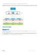
The following illustration shows VLT deployed on S5000 switches. The switches appear as a single virtual switch from the point of view of
the switch or server supporting LACP.
Figure 142. Virtual Link Trunking on S5000 Switches
VLT on Core Switches
You can also deploy VLT on core switches.
Uplinks from servers to the access layer and from access layer to the aggregation layer are bundled in LAG groups with end-to-end Layer 2
multipathing. This set up requires “horizontal” stacking at the access layer and VLT at the aggregation layer such that all the uplinks from
servers to access and access to aggregation are in Active-Active Load Sharing mode. This example provides the highest form of resiliency,
scaling, and load balancing in data center switching networks.
976
Virtual Link Trunking (VLT)