
Owners Manual


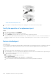


Table Of Contents
- Dell EMC PowerStore Installation and Service Guide for PowerStore 1000, 3000, 5000, 7000, and 9000 Models
- Contents
- Additional Resources
- Install a new base enclosure and optional expansion enclosure
- Install a new base enclosure
- Install a 25-drive expansion enclosure
- Summary of tasks for installing an expansion enclosure
- Verify shipping package contents
- Choose where to install the expansion enclosure
- Removing a filler panel
- Install the rails in the cabinet
- Install the expansion enclosure on the rails
- Installing drives
- Installing the front bezel
- Cable the base enclosure to the expansion enclosure
- Connect expansion enclosure power cables
- Verify the operation of the new part
- Add a 25-drive expansion enclosure
- Summary of tasks for adding an expansion enclosure
- Verify shipping package contents
- Choose where to install the expansion enclosure
- Removing a filler panel
- Install the rails in the cabinet
- Install the expansion enclosure on the rails
- Installing drives
- Installing the front bezel
- Connect expansion enclosure power cables
- Cable the base enclosure to the new expansion enclosure
- Verify the operation of the new part
- Base enclosure service procedures
- Replace a faulted drive in the base enclosure
- Add a new drive to the base enclosure
- Replace a power supply
- Replace an embedded module
- Replace a 4-port card
- Replace an SFP
- Replace an I/O module
- Replace a fan module
- Replace a dual inline memory module (DIMM)
- Identify a faulted part from PowerStore Manager
- Power down the node
- Remove the node
- Remove the top cover from the node
- Remove the faulted dual inline memory module
- Install the dual inline memory module
- Install the top cover on the node
- Install the node
- Power up the node
- Verify the operation of a replacement part
- Return a faulted part
- Replace an internal M.2 boot module
- Identify a faulted part from PowerStore Manager
- Power down the node
- Remove the node
- Remove the top cover from the node
- Remove the faulted internal M.2 boot module
- Install the internal M.2 boot module
- Install the top cover on the node
- Install the node
- Power up the node
- Verify the operation of a replacement part
- Return a faulted part
- Replace an M.2 boot module adaptor
- Identify a faulted part from PowerStore Manager
- Power down the node
- Remove the node
- Remove the top cover from the node
- Remove the faulted M.2 boot module adaptor
- Install the M.2 boot module adaptor
- Install the top cover on the node
- Install the node
- Power up the node
- Verify the operation of a replacement part
- Return a faulted part
- Replace a node
- Identify a faulted part from PowerStore Manager
- Power down the node
- Remove the node
- Remove the top cover from the node
- Transfer parts from the faulted node to the replacement node
- Transfer the internal battery backup module
- Install the top cover on the node
- Install the node
- Power up the node
- Verify the operation of a replacement part
- Return a faulted part
- Expansion enclosure service procedures
- Safety precautions for handling replaceable units
- Discovering PowerStore Appliances
- Power control procedures
- Power control procedure considerations
- Power control procedures preview
- Powering off procedures for PowerStore node
- Powering on procedures for PowerStore node
- Rebooting procedures for a PowerStore node
- Powering off procedures for PowerStore appliances
- Powering on procedures for PowerStore appliances
- Powering off procedures for PowerStore cluster
- Powering on procedures for PowerStore cluster
- Data collection
- Support Notifications
- Reinitialize the system

Replace a power/cooling module in a 25-drive
expansion enclosure
Take the following actions to remove the faulted power/cooling module from the 25-drive expansion enclosure and install a
replacement power/cooling module.
Identify a faulted part from PowerStore Manager
Before you replace a part, ensure that you have identified its location within the system. Using PowerStore Manager, you can
identify and locate a faulted part.
Steps
1. From PowerStore Manager, select Hardware.
2. Select the appliance that contains the faulted part.
3. From the Hardware card, select the view of the system where the faulted part is located.
Faulted parts appear in red in the image of the system, and report a status of Faulted in the State field.
Removing a faulted power/cooling module
Prerequisites
Identify the faulted power/cooling module by the amber fault LED.
CL5987
#
#
Figure 131. Fault LED on an AC power/cooling module
About this task
CAUTION:
Access to the drives in your enclosure will time out and the drives will spin down two minutes after
a power cooling module is removed from the enclosure. While the system can continue operating on a single
power supply, the loss of two blowers causes the DAE to power down unless you replace the module within two
minutes. When replacing both cooling modules, ensure that the green light on one module has been steadily on
for at least 5 seconds before removing power from the second module.
Steps
1. Attach an ESD wristband to your wrist and the enclosure.
2. On an AC power/cooling module, release the cable retention bail, and unplug the power cord.
104
Expansion enclosure service procedures