
Setup Guide


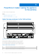


Table Of Contents
- Dell EMC PowerStore Networking Guide for PowerStore X Models
- Contents
- Additional Resources
- Overview
- Prepare to configure switches and networks
- PowerStore X model: Network configuration requirements
- Configuring with Dell EMC PowerSwitch Series S4148-ON switches
- Configuring with Dell EMC PowerSwitch Series S4148-ON switches overview
- Get the completed Network Setup Preparation Worksheet
- Establish a terminal session to the switch
- Validate the switch version and licensing
- Configure general settings on the Top-of-Rack (ToR) switches
- Configure PowerStore X model network VLANs on the switch
- Configure Virtual Link Trunking interconnect (VLTi)
- Configure the uplink ports on the Top of the Rack (ToR) switches
- PowerStore X model: Cabling the appliance to the switches
- Validate switch and network configuration
- Discovering PowerStore Appliances
- Initial configuration of the PowerStore X model appliance
- Expand a Storage network to run across multiple ports
- Create an additional Storage network
- Other Dell EMC PowerSwitch Series S4148-ON switch configuration operations

PowerStore X model: Cabling the appliance
to the switches
This chapter contains the following information.
Topics:
• Cable the base enclosure to the ToR switches
• Cable the ToR switches together
• Cable the Top-of-Rack switches to the core uplinks
Cable the base enclosure to the ToR switches
Cable the nodes to the Top of Rack (ToR) switches.
2
4
1 3
Figure 5. Base enclosure connection to the ToR switches
As demonstrated in the diagram, when cabling the nodes to the ToR switches:
● Port 0 and Port 1 on the same node must connect to opposite switches
● Port 0 on Node A, and Port 0 on Node B must connect to opposite switches
● Port 1 on Node A, and Port 1 on Node B must connect to opposite switches
Table 13. Steps to cable to the switches
1 Connect Port 0 of the bottom node (A) to Port 1 of the bottom switch (1).
2 Connect Port 1 of the bottom node (A) to Port 1 of the top switch (2).
3 Connect Port 1 of the top node (B), to Port 54 of the bottom switch (1).
5
34 PowerStore X model: Cabling the appliance to the switches