
Owners Manual


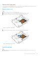

Table Of Contents
- Dell EMC PowerStore Installation and Service Guide for PowerStore 1000, 3000, 5000, 7000, and 9000 Models
- Contents
- Additional Resources
- Install a new base enclosure and optional expansion enclosure
- Install a new base enclosure
- Install a 25-drive expansion enclosure
- Summary of tasks for installing an expansion enclosure
- Verify shipping package contents
- Choose where to install the expansion enclosure
- Removing a filler panel
- Install the rails in the cabinet
- Install the expansion enclosure on the rails
- Installing drives
- Installing the front bezel
- Cable the base enclosure to the expansion enclosure
- Connect expansion enclosure power cables
- Add a 25-drive expansion enclosure
- Summary of tasks for adding an expansion enclosure
- Verify shipping package contents
- Choose where to install the expansion enclosure
- Removing a filler panel
- Install the rails in the cabinet
- Install the expansion enclosure on the rails
- Installing drives
- Installing the front bezel
- Connect expansion enclosure power cables
- Cable the base enclosure to the new expansion enclosure
- Base enclosure service procedures
- Replace a faulted drive in the base enclosure
- Add a new drive to the base enclosure
- Replace a power supply
- Replace an embedded module
- Replace a 4-port card
- Before you begin
- Identify a faulted 4-port card from PowerStore Manager
- Identify a faulted part from PowerStore Manager
- Embedded module LEDs
- Power down the node
- Remove an embedded module
- Remove a 4-port card
- Install a 4-port card
- Install an embedded module
- Power up the node
- Verify the operation of a new 4-port card
- Return a faulted part
- Replace an SFP
- Replace an I/O module
- Replace a fan module
- Before you begin
- Identify a faulted fan module from PowerStore Manager
- Power down the node
- Remove the node
- Remove the top cover from the node
- Remove the faulted fan module
- Install a new fan module
- Install the top cover on the node
- Install the node
- Power up the node
- Verify the operation of a replacement fan module
- Return a faulted part
- Replace a dual inline memory module (DIMM)
- Before you begin
- Identify a faulted DIMM from PowerStore Manager
- Power down the node
- Remove the node
- Remove the top cover from the node
- Remove the faulted dual inline memory module
- Install the dual inline memory module
- Install the top cover on the node
- Install the node
- Power up the node
- Verify the operation of a replacement DIMM
- Return a faulted part
- Replace an internal M.2 boot module
- Before you begin
- Identify a faulted internal M.2 boot module from PowerStore Manager
- Power down the node
- Remove the node
- Remove the top cover from the node
- Remove the faulted internal M.2 boot module
- Install the internal M.2 boot module
- Install the top cover on the node
- Install the node
- Power up the node
- Verify the operation of a replacement internal M.2 boot module
- Return a faulted part
- Replace an M.2 boot module adaptor
- Before you begin
- Identify a faulted M.2 boot module adaptor from PowerStore Manager
- Power down the node
- Remove the node
- Remove the top cover from the node
- Remove the faulted M.2 boot module adaptor
- Install the M.2 boot module adaptor
- Install the top cover on the node
- Install the node
- Power up the node
- Verify the operation of a replacement M.2 boot module adaptor
- Return a faulted part
- Replace a node
- Before you begin
- Identify a faulted node from PowerStore Manager
- Power down the node
- Remove the node
- Remove the top cover from the node
- Transfer parts from the faulted node to the replacement node
- Install the top cover on the node
- Install the node
- Power up the node
- Verify the operation of a replacement node
- Return a faulted part
- Expansion enclosure service procedures
- Safety precautions for handling replaceable units
- Power control procedures
- Power control procedure considerations
- Power control procedures preview
- Powering off procedures for PowerStore node
- Powering on procedures for PowerStore node
- Rebooting procedures for a PowerStore node
- Powering off procedures for PowerStore appliances
- Powering on procedures for PowerStore appliances
- Powering off procedures for PowerStore cluster
- Powering on procedures for PowerStore cluster
- Transferring the internal battery backup module
- Data collection
- Support Notifications
- Reinitialize the system

Figure 23. Removing a drive filler module
Install a 2.5" drive
About this task
NOTE:
If you are installing multiple drives in a system that is powered up, wait at least 10 seconds before sliding the next
drive into position.
Steps
1. Align the drive with the guides in the slot.
2. With the latch fully opened, gently push the drive into the slot.
The latch begins to rotate downward when it meets the enclosure.
3. Push the orange button until the drive is fully seated in the slot.
4. Push the latch down until it locks into place.
Base enclosure service procedures
31